
Four Stage FM Transmitter Circuit PCB
The FM transmitter circuit consists of four key stages, each serving a specific function to ensure efficient signal generation and amplification.
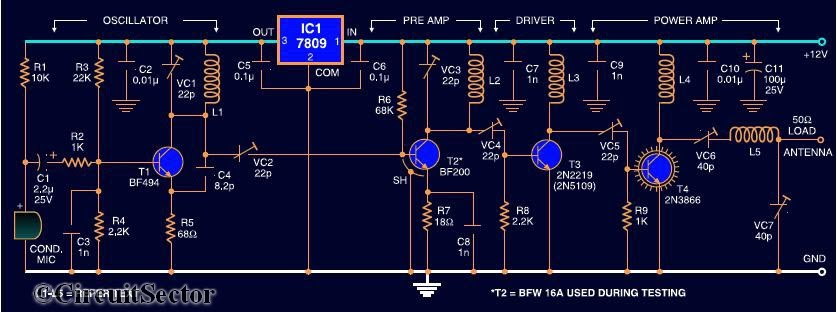
1. **VHF Oscillator Stage**: The circuit begins with a VHF oscillator, which is crucial for generating the carrier frequency for the FM transmission. This stage utilizes the BF494 transistor, known for its high-frequency performance. The oscillator design typically involves a tank circuit consisting of inductors and capacitors that determine the frequency of oscillation. The output of this stage is a modulated signal that varies in frequency according to the audio input.
2. **Pre-Amplifier Stage**: The next stage is the pre-amplifier, which employs the BF200 transistor. This stage amplifies the weak signals generated by the oscillator to a level suitable for further amplification. The pre-amplifier is designed to have a high input impedance to avoid loading the oscillator circuit and a low output impedance to drive the next stage effectively.
3. **Driver Stage**: Following the pre-amplifier, the driver stage consists of the 2N2219 transistor. This stage provides additional gain and prepares the signal for the final power amplification. The driver stage is essential for ensuring that the signal is robust enough to be amplified without distortion, maintaining the integrity of the audio information being transmitted.
4. **Power Amplifier Stage**: The final stage of the circuit is the power amplifier, which utilizes the 2N3866 transistor. This stage is responsible for boosting the signal to a level suitable for transmission over longer distances. The power amplifier must be designed to handle higher currents and voltages while minimizing distortion. Proper heat dissipation techniques, such as heatsinks, are often employed to ensure reliable operation.
Overall, the four-stage design of this FM transmitter allows for effective modulation and amplification of signals, enabling clear and reliable radio transmission. The careful selection of transistors and circuit configuration is critical for achieving the desired performance characteristics in terms of frequency stability, output power, and signal quality.Here`s the circuit diagram of a four RF stage FM transmitter. The stages are, very high frequency (VHF) oscillator built around a HF transistor BF494, a pre- amplifier built around transistor BF200, a driver transistor 2N2219 and a power amplifier using 2N3866. 🔗 External reference
Related Circuits
This circuit consists of a 6 Zone Alarm system with an LED display. The alarm system features 6 independent zones and includes a 7-segment LED display, along with one timed entry/exit zone. The 6 Zone Alarm system is designed to...
When there is a need to amplify audio signals from various sources before they reach a custom amplifier, a preamplifier (or preamp) is typically employed. This document suggests a specific circuit that is interesting due to its use of...
VOX is a voice-activated switch commonly used with microphones as an alternative to traditional push-button switches. The VOX can be connected to various audio equipment featuring an external speaker for coupling. The activation threshold is adjusted using the volume...
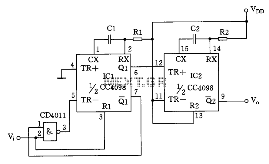
The circuit depicted features a double oscillator utilizing a monostable multivibrator CC4098 and a quad 2-input NAND gate CC4011, among other components. This circuit allows for adjustable frequency and duty cycle. It is primarily designed as a keying oscillator,...
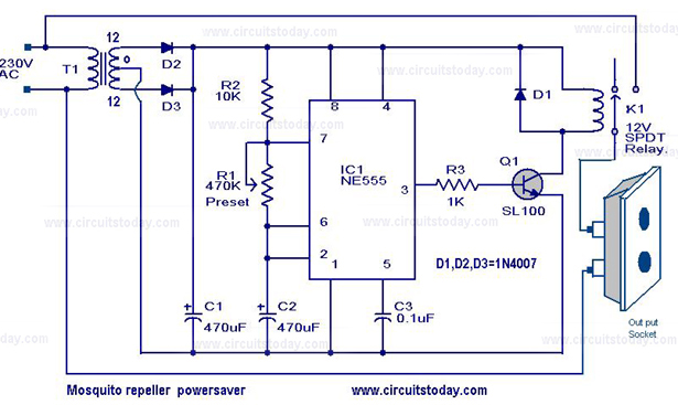
The circuit diagram of a mosquito repellent power saver circuit is provided along with a detailed explanation. The mosquito repellent power saver circuit is designed to efficiently operate a mosquito repellent device while minimizing energy consumption. This circuit typically integrates...
This hybrid circuit uses a mixture of transistors, an IC and a relay and is used to automatically open or close a pair of curtains. Using switch S3 also allows manual control, allowing for curtains to be left only...
Warning: include(partials/cookie-banner.php): Failed to open stream: Permission denied in /var/www/html/nextgr/view-circuit.php on line 713
Warning: include(): Failed opening 'partials/cookie-banner.php' for inclusion (include_path='.:/usr/share/php') in /var/www/html/nextgr/view-circuit.php on line 713