
Mosquito repeller power saver circuit and energy saver circuit diagram
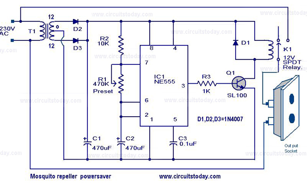
The mosquito repellent power saver circuit is designed to efficiently operate a mosquito repellent device while minimizing energy consumption. This circuit typically integrates a microcontroller or a timer IC, which controls the activation and deactivation of the repellent device based on predefined intervals.
The schematic may include essential components such as resistors, capacitors, and transistors, which help in regulating the power supply and ensuring that the device operates within safe limits. A common configuration might involve a 555 timer IC, which can be set up in astable mode to generate a square wave output. This output can be used to drive a transistor that acts as a switch, turning the repellent device on and off at specified intervals.
Power supply considerations are crucial; the circuit may require a regulated DC source, often derived from an AC mains supply through a transformer and rectifier setup. Additionally, the use of a capacitor for smoothing the rectified voltage is typical to ensure stable operation.
For enhanced efficiency, the circuit design may incorporate features such as a low-power mode, where the microcontroller or timer IC consumes minimal energy during inactive periods. This approach not only prolongs the life of the power source but also reduces overall energy costs associated with the operation of the mosquito repellent device.
The layout of the circuit should be carefully designed to minimize interference and optimize the performance of the components. Proper placement of the components and routing of the connections are essential to ensure reliable operation and to prevent issues such as noise or voltage drops that could affect the functioning of the circuit.
Overall, this mosquito repellent power saver circuit serves as an effective solution for maintaining pest control while being energy efficient, making it suitable for both residential and commercial applications.The circuit diagram of a mosquito repellent power saver circuit is given with a detailed explanation.. 🔗 External reference
Related Circuits
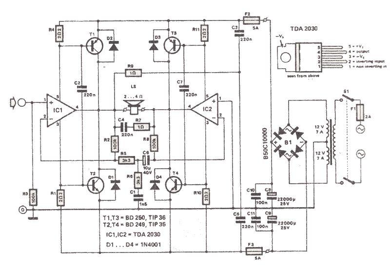
The TDA2030 is a low-cost audio power amplifier capable of delivering high output audio power up to 200 watts with a load impedance of 2 to 4 ohms. This high-power audio amplifier is built around the TDA2030 audio amplifier...
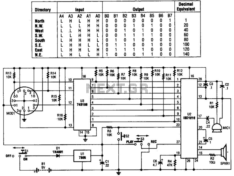
A talking compass consists of a Hall-effect direction sensor (MODI) and an ISD1016 analog audio storage device. It can store eight two-second announcements for each of the eight primary compass directions. The Talking Compass includes a digital compass (MODI),...
Electronic Schematic Circuit Diagrams Manual PDF Download. The document provides a comprehensive manual that focuses on electronic schematic circuit diagrams. These diagrams are essential tools for understanding and designing electronic circuits, offering visual representations of circuit components and their interconnections....
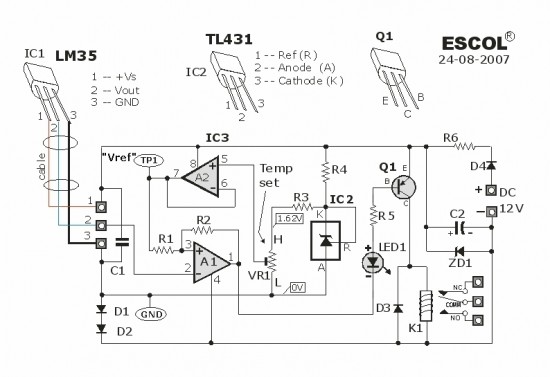
This temperature-controlled relay circuit is a simple yet highly accurate thermal control circuit that can be used in applications requiring automatic temperature regulation. The temperature-controlled relay circuit operates by monitoring the ambient temperature and activating or deactivating a connected load...
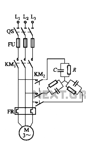
The circuit illustrated in Figure 3-151 consists of capacitor banks arranged in a specific configuration. Figure 3-151 (a) depicts capacitor banks connected in a shaped configuration, which is suitable for shaped or Y-connected motors. Figure 3-151 (b) shows Y-connected...
The GPS interface can be fed in 2 ways: with a stabilized 5V supply or with a 10 to 25V unregulated DC supply. In both cases, the power is fed into the RJ45 connector on point 8. Pin 7...