
Four-way operation of the dynamic braking circuit
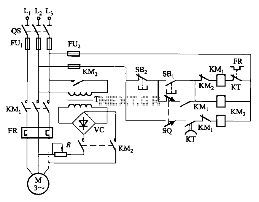
The circuit utilizes a limit switch to ensure precise control of motor operations. The limit switch (SQ) is strategically placed to detect when the mechanical device has reached its designated position. Upon activation, the limit switch interrupts the power supply to the motor, effectively stopping its operation. This is crucial in applications where overshooting the target position could lead to mechanical damage or operational inefficiencies.
In addition to power interruption, the circuit employs dynamic braking, a technique that utilizes the motor's own back EMF to rapidly decelerate the mechanical device. This is achieved by rerouting the motor's terminals to create a short circuit, allowing the motor to act as a generator. The generated current dissipates energy, leading to a swift stop. This feature is particularly beneficial in applications requiring quick response times and high precision, such as automated machinery, CNC machines, and robotic systems.
The integration of the limit switch and dynamic braking enhances the safety and reliability of the machine circuit. By ensuring that the motor ceases operation at the correct moment, the risk of mechanical wear and tear is minimized, thereby extending the lifespan of the equipment. Furthermore, this configuration allows for smooth transitions between operational states, reducing the likelihood of sudden jerks or movements that could compromise the integrity of the system or the safety of operators.
Overall, the circuit design exemplifies effective motor control through the combination of limit switches and dynamic braking, making it an essential component in modern automated systems. Circuit shown in Figure 3-136. The line adds a limit switch SQ, when the motor is running with a mechanical device to a predetermined position, turn off the power and dynamic b raking for fast, accurate positioning. Commonly used in the machine circuit.
Related Circuits
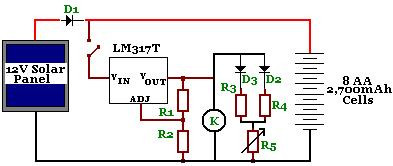
The circuit is designed to power a CCTV camera, provide lighting inside a nestbox, and charge batteries using a photovoltaic (PV) solar panel. It includes a circuit diagram for a solar-powered wireless CCTV camera with battery backup. D1 is...
Most 24V power systems in trucks, 4WDs, RVs, boats, and similar applications utilize two series-connected 12V lead-acid batteries. The charging system is designed to maintain the total voltage of the two batteries. If one battery begins to fail, the...
Based on the classic Baxendall tone control circuit, this provides a maximum cut and boost of around 10dB at 10K and 50Hz. As the controls are passive, the last transistor provides a slight boost. The output is designed to...
The USB charger power supply is designed for use in MP3 and MP4 chargers. It accepts an input of AC 160-240V at 50/60Hz and has a rated output of DC 5V at 250mA. For applications requiring a long-term higher...
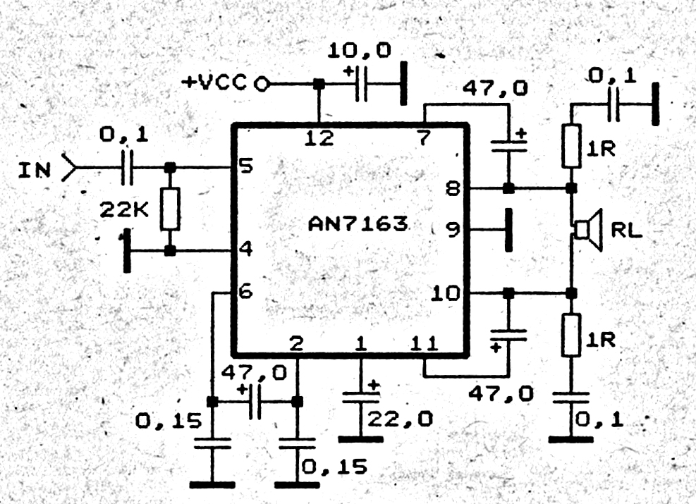
This 5.1 surround amplifier circuit schematic utilizes the IC AN7168 as the primary component. The circuit requires a minimum voltage of 12V and a maximum voltage of 24V, with a recommendation of 12V due to the voltage ratings of...
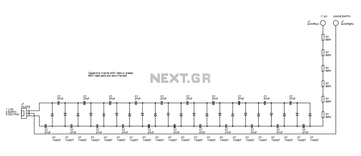
A basic mains driven Cockroft ladder high voltage generator is shown in the schematic. This is functionally the same as a project in Electronics Today International many years ago. The peak mains voltage of 340V appears across each capacitor...