
Receiver Af Noise Limiter For Low-Level Signals Circuit
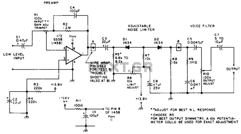
The audio preamplifier circuit is designed to enhance weak audio signals, typically ranging from 10 mV to 1 V, ensuring that these signals can be processed effectively by subsequent stages, such as a diode clipper. The primary function of the preamplifier is to increase the amplitude of the input signal while maintaining signal integrity and minimizing noise.
The circuit typically consists of a transistor or operational amplifier configured in a non-inverting amplifier configuration, providing a high input impedance to avoid loading the signal source. This high input impedance is crucial for preserving the quality of the audio signal, especially when dealing with sensitive sources like microphones or low-level audio outputs.
The gain of the preamplifier can be adjusted through feedback resistors, allowing for flexibility in accommodating various input levels. Capacitors may be used for coupling and decoupling to block DC offsets while allowing AC audio signals to pass through. Additionally, the power supply for the preamplifier must be sufficiently stable to prevent fluctuations that could introduce noise into the amplified signal.
Following amplification, the signal is fed into a diode clipper, which serves to limit the amplitude of the signal to prevent distortion that can occur when the signal exceeds a certain threshold. The diode clipper circuit typically consists of diodes arranged in a configuration that allows for clipping of both the positive and negative peaks of the audio waveform, thus shaping the output signal for further processing or amplification.
Overall, this combination of a preamplifier and diode clipper is essential in audio processing applications where signal integrity and control of signal levels are paramount, ensuring the final output remains within acceptable limits for subsequent stages in the audio chain. A preamplifier in the audio frequency range amplifies a noisy audio signal to drive a diode clipper. Suitable audio input levels would be in the 10-mV to 1-V range. 🔗 External reference
Related Circuits
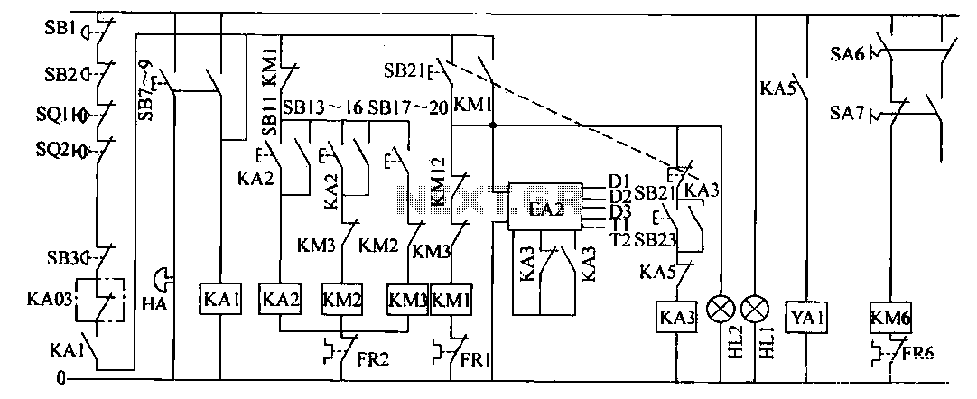
The operation control circuit is primarily managed by the button switch SB21. The contactor KM1, composed of the main contactor KM1, directly controls the operation of the main motor M1. The main motor M1 serves as the prime mover,...
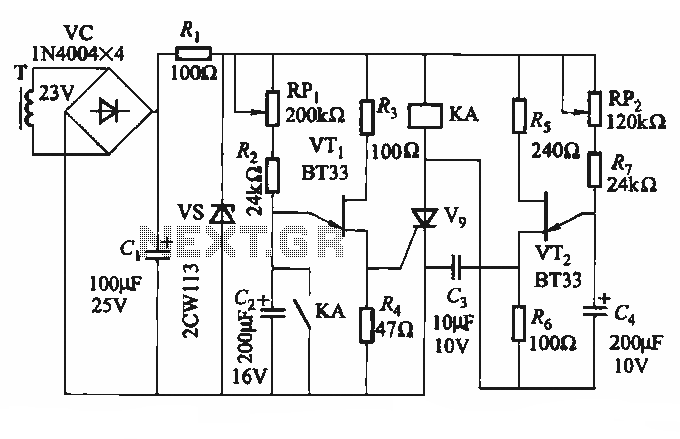
The circuit depicted in Figure 3-69 is designed for applications requiring frequent timing control for motor reversing operations. In this configuration, thyristors V1, V2, and V7 are utilized for positive control of motor rotation, while thyristors V3, V4, V5,...
To achieve optimal audio reproduction at varying listening levels, it is essential to adjust tone control settings to align with the established characteristics of human auditory perception. The sensitivity of the human ear changes non-linearly across the entire audible...

A simple device that enables a quick check of common infrared remote controls can be beneficial for electronics enthusiasts often tasked with repairing or testing these widely used devices. A dependable circuit has been designed using a few components:...
This circuit was built to charge two series lithium cells (3.6 volts each, 1 Amp Hour capacity) installed in a portable transistor radio. The circuit is designed to efficiently charge two lithium-ion cells connected in series. Each cell has a...
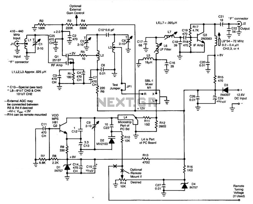
Ll, Ql, L2, and L3 form an RF amplifier stage that feeds Ml, a doubly balanced mixer. Q4 is a local oscillator stage operating in the 375-MHz range. Signals in the 420- to 450-MHz range from Ql are mixed...