
FPGA DC Motor Control Circuit

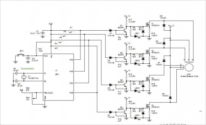
The schematic for the motor control circuit integrates a CPLD (Complex Programmable Logic Device) and an FPGA (Field Programmable Gate Array), both of which are essential for managing various I/O operations. The large number of I/O pins associated with these devices necessitates careful organization of the schematic to avoid confusion. The motor control circuit, as the primary focus, is strategically designed to interface with the CPLD, which coordinates the motor's operation.
The inclusion of a capacitor near the motor controller IC is critical for maintaining a stable current supply to the motors, thus enhancing performance during operation. This capacitor acts as a filter, smoothing out any voltage fluctuations that may occur, which is particularly important during the rapid switching of the motor control signals.
The MAX150 component is utilized for its capability to continuously convert analog signals, ensuring that the data is promptly available for processing. The WR pin is a crucial control signal that triggers the MAX150 to update its output, allowing the CPLD to read the latest data without delay.
Furthermore, the PWM (Pulse Width Modulation) output capability of this circuit allows for simultaneous control of both the motors and the LEDs. This dual functionality not only provides visual feedback through LED brightness but also enables precise control of the motor's speed and direction. The schematic clearly delineates the connections between the CPLD, motor controller, and the LED outputs, ensuring that the design is both efficient and effective in its operation.
Overall, this schematic represents a well-structured approach to integrating complex components while maintaining clarity and functionality within the design.An issue with CPLD and FPGA devices is that they have so many I/O pins that their schematics become overwhemlingly HUGE very quickly. I tried my best to partition out different sections of the schematic to show the motor control circuit, a-to-d converter circuit and left-over LED output circuit.
The motor control circuit is the main focus as it i s the new addition to this board. As you can see in the schematic, we`re basically wiring things up to power, ground and 2 wires go to the CPLD. A capacitor is added near the motor controller IC to make sure that it can provide a steady flow of current to the motors.
This circuit is unchanged from the CPLD A-to-D article. The MAX150 is in a constantly converting mode whenever the WR pin is asserted it updates. The CPLD takes care of this for us. This circuit is also left over from the previous article, but I feel it makes a great addition as we can output the PWM signal to the LEDs as well as to the motor controller, this way we can really see the direction/speed control in two forms: in motor movement and in LED`s brightness. 🔗 External reference
Related Circuits
The threaded drive rod was constructed using standard 5/16 inch Whitworth threaded rod (18 TPI) due to availability, although M8 metric threading could have been an alternative. The radius of the curve in the drive rod, which must equal...
This infrared alarm barrier is designed to detect individuals passing through doorways, corridors, and small gates. The transmitter emits a beam of infrared light that remains invisible to the human eye. When a person interrupts the light beam, the...
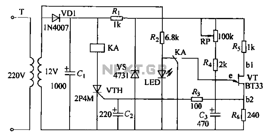
The circuit consists of a delay loop, discriminators, output circuits, power supply, and indicator lights, divided into five parts. The power regulation is achieved through a resistor (R), while the power regulator is constructed using a voltage source. In...

Remote Control Mains Switch The remote control mains switch is a device designed to control the power supply to electrical appliances from a distance, typically utilizing a wireless remote control. This switch can be integrated into various applications where remote...
NEC's UPB1008K is a Silicon RFIC specifically designed for handheld low-power, low-cost GPS receivers. The integrated circuit combines a low-noise amplifier (LNA) followed by a double-conversion RF/IF downconverter block and a phase-locked loop (PLL) frequency synthesizer on a single...
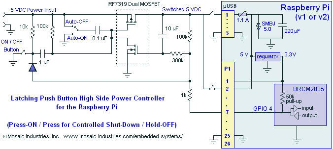
A momentary contact push button switch can be utilized to conveniently turn the Raspberry Pi (RPi) ON and OFF. Pressing the button will apply power to the micro USB header, maintaining power while the Raspberry Pi initializes and starts...