
Barn Door motor driven Mounts
On the left side (hinge side), a mounting plate for a ball and socket head was bent to ensure that the ball and socket head was approximately horizontal when the barn door is aligned with local latitude. The mounting for the gunsight is located near the center of the top board. On the right side, a plate supports a gimbal bearing that secures the top end of the drive rod. The center of the drive rod gear was cut away to accommodate a captive drive nut, which was created by soldering a standard threaded nut into a drilled mild steel plate. This assembly was then bolted centrally onto the drive gear. Components for the drive system were sourced from various old printers. The drive gears measure approximately 70mm in diameter for the drive rod and 50mm for the stepper motor, providing a slight gearing advantage for the motor.
The plastic bush used for the lower bearing support was also salvaged from an old printer. Its center was drilled out to allow a loose fit around the drive rod. The lower barn door panel was drilled to retain the lower section of the plastic bush, and the surrounding area was routed to sink the shoulder of the plastic bush, ensuring that the captive drive nut was nearly level with the upper surface of the panel. Final height adjustments were made using a shim washer beneath the shoulder. A thin brass washer was placed between the upper plastic bearing surface and the lower side of the captive nut, with a small amount of lubricating grease applied to minimize friction in this bearing.
The stepper motor was installed into the lower barn door panel (again using a router) to align the motor gear with the drive rod gear, allowing for gear meshing adjustments. The original tripod mounting plate on the underside of the bottom panel remained intact, having been drilled and tapped to 1/4 inch BSW at several locations to provide balanced mounting points based on the weight of the camera and lens used. The total weight of the camera and large zoom lens was around 5lbs, while the barn door added approximately 7lbs, resulting in a total weight of 12lbs (4.7kg), exceeding the design maximum of 10lbs for the tripod head. This excess weight caused some flexing when the barn door was driven outwards, which was resolved by removing the tripod head, installing an equatorial wedge, and securing the wedge directly to the tripod.
Given the substantial weight of the barn door and camera/lens combination, a reasonably powerful motor was necessary. The selected unipolar stepper motor (also sourced from an old printer) had winding resistances of 39 ohms and a diameter of 55mm. When powered by a 12-volt supply, drawing approximately 0.32 amps in single-step mode, the motor provided sufficient torque to operate the barn door effectively. The use of a unipolar stepper motor simplified the drive circuitry, which primarily utilized transistors to switch each of the motor phases. This configuration allows for precise control over the motor's movement, ensuring smooth operation of the barn door mechanism.The threaded drive rod was made from standard 5/16 inch Whitworth threaded rod (18 TPI), only because this was to hand. M8 metric thread could have been used. The radius of the curve in the drive rod (which must be equal to the distance between the hinge and the drive rod) was 300mm.
As this drive and it`s angular drive rate were to be controlled via a computer, this dimension and thread type are not critical. The controlling software could be set up to match. Many simple barn door designs use a straight drive rod which is rotated within a fixed drive nut. This is not possible when using a curved drive rod. A curved drive rod must be constrained at one end by a gimbal mount so that the drive rod cannot rotate. The drive nut must be free to be driven to rotate round the drive rod. - on the left hand side (ie hinge side), a mounting plate for ball and socket head. This was bent so that the ball and socket head was approximately horizontal when the barn door is set for local latitude.
- mounting for the gunsight is situated near the middle of the top board. To the right hand side is a plate supporting a gimbal bearing that fixes the top end of the drive rod. The centre of the drive rod gear was cut away to make room for a captive drive nut. The captive drive nut was made by soldering an ordinary threaded nut into a drilled mild steel plate.
This was then bolted exactly centrally onto the drive gear. Parts associated with the drive system were obtained (collected ) from various old printers. The drive gears are approximately 70mm diameter for the drive rod and 50mm diameter for the stepper motor, so there is a small gearing advantage for the motor stepper motor. Again, the plastic bush that was used for the lower bearing support was found in an old printer. This centre of this bush was drilled out to be a loose/working fit around the drive rod. The lower barn door panel was drilled through to retain the lower/narrower section of the plasic bush.
The surrounding area was routered to sink the shoulder of the plastic bush a depth which resulted in the captive drive nut being approximately level with the upper surface of this panel. Final adjustment of height was done by including a `shim` washer underneath the shoulder. A thin brass washer was fitted between the upper plastic bearing surface and the lower side of the captive nut.
A little lubricating grease was applied to reduce friction in this bearing. The stepper motor was fitted into the lower barn door panel (again by use of a router) so that the motor gear matched the height of the drive rod gear and so that the meshing of the gears could be adjusted. The original tripod mounting plate on the underside of the bottom panel has been left in place. This had been drilled and tapped to 1/4 inch BSW at several points so as to provide balanced mounting points, depending on the weight of camera/lens used.
The total weight of the camera and large zoom lens was around 5lbs. The barn door added another 7lbs or so. The total weight of 12lbs (4. 7kg) was more than the design maximum of 10lbs for the tripod head and resulted in some flexing as the barn door was driven outwards. The flexing was eliminated removing the tripod head, fitting an equatorial wedge as shown in the image above, and fastening the wedge directly onto the tripod.
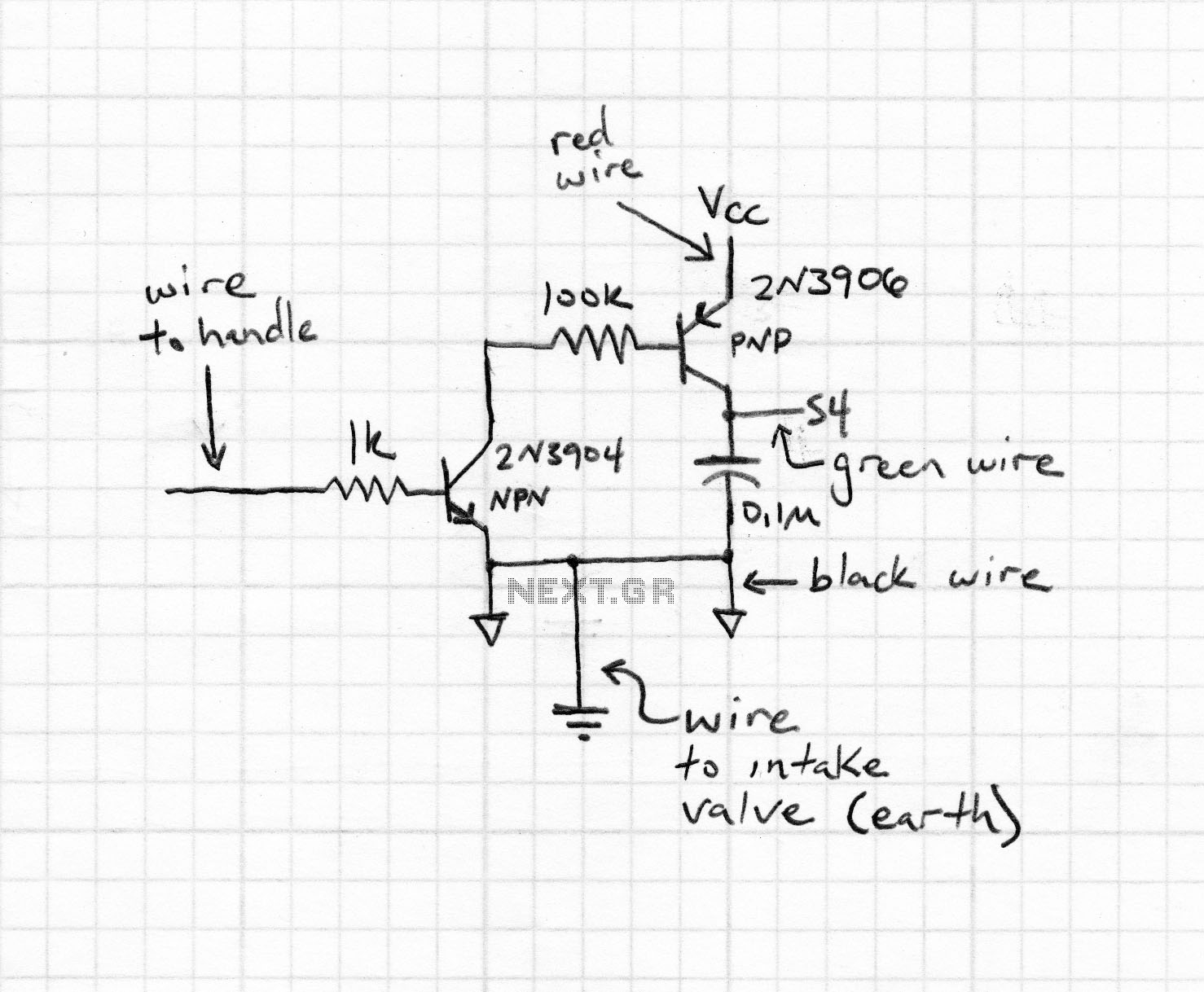
Considering the substantial weight of barn door and camera/lens, a reasonably powerful motor was needed. The uni-polar stepper motor selected (again from an old printer) was marked as having winding resistances of 39 ohms.
The motor itself was 55mm diameter. No other meaningful information was given. When driven from a 12 volt supply (and therefore drawing a current of approx 0. 32 amps in single step mode), there was clearly sufficient torque available to drive the barn door. Using a unipolar stepper motor kept the drive circuitry fairly simple. In essence, transistors are used to switch each of t 🔗 External reference
Related Circuits
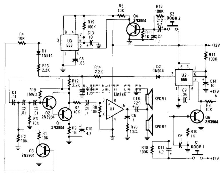
When the pushbuttons at either door are pressed, this circuit produces a distinct tone for each door. The tones are generated by a phase-shift oscillator comprising transistors Q1 and Q2. Transistor Q3 modifies the tone frequency by altering the...
The following circuit illustrates the circuit diagram of a motor control unit. This circuit is based on the LM317 integrated circuit (IC). Features include diodes that protect the regulator. The motor control unit circuit utilizes the LM317 voltage regulator to...
A DC motor from an old personal stereo cassette player has been utilized in this circuit, which provides control over both the speed and direction of the motor. The circuit employs PWM waveforms to drive a MOSFET H-bridge, as...
The electronic motor speed controller circuit includes a wireless remote control transmitter circuit and a wireless remote control receiver circuit, as illustrated in the accompanying chart. The wireless remote control transmitter circuit comprises a micro-power wireless remote control transmitter...
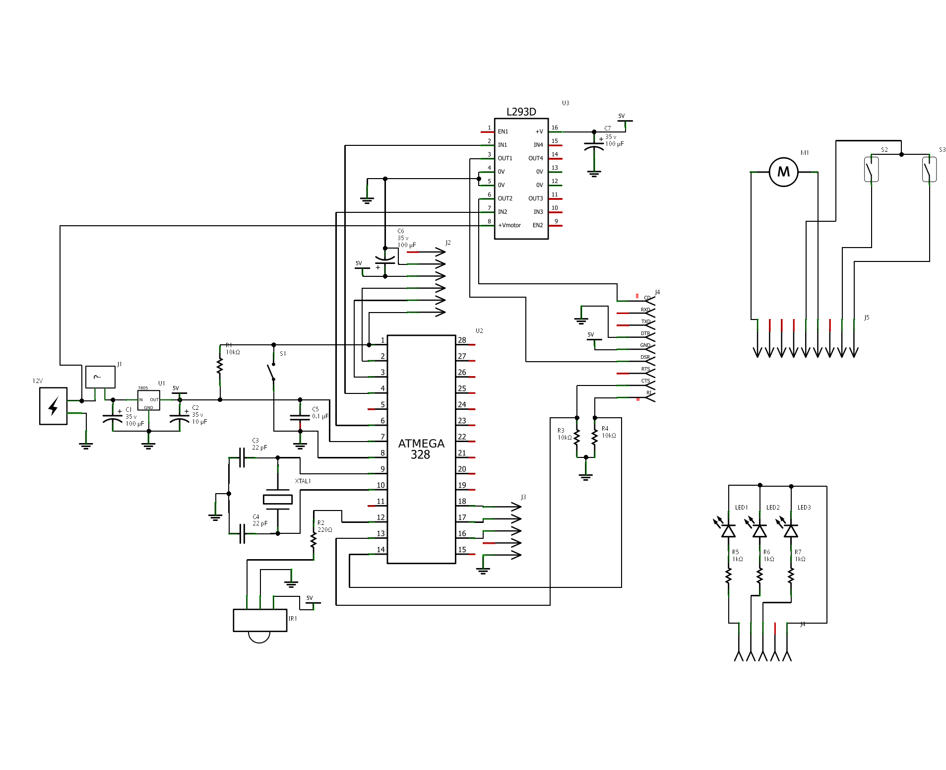
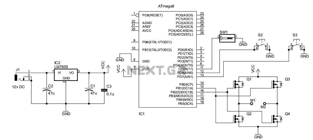
The project is "Motorized Curtain" with Remote control. It is made up of MCU ATMEGA328 with Arduino BootLoader, motor driver L293D (I used L293B with external diodes, because I couldn't find L293D), IR Receiver TSOP 1738, DC Motor from...

The circuit connection is illustrated in figures a and b. In figure a, a star-shaped winding is used with shunt capacitance, while figure b depicts a triangular winding with capacitance connected in parallel. The working capacitance (Cc) is calculated...