
Free energy generating coil
Warning: Undefined array key "extension" in /var/www/html/nextgr/view-circuit.php on line 468
Deprecated: strtolower(): Passing null to parameter #1 ($string) of type string is deprecated in /var/www/html/nextgr/view-circuit.php on line 468

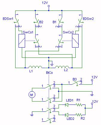
The described circuit configuration involves a power coil integrated with disk magnets at both ends, which are crucial for the generation of charge through electromagnetic principles. The pulse charging of the coil induces a transient magnetic field that interacts with the permanent magnets, leading to a repulsion effect that creates potential energy. This potential energy is harnessed when the electromagnetic field collapses, allowing the system to generate a charge without mechanical movement.
The isolation of the charge and output circuits via a DPDT Reed Switch ensures that the generated charge is not affected by the load conditions, maintaining circuit integrity. The use of a bifilar winding technique, as seen in the Joule Thief design, enhances the efficiency of the energy transfer, allowing for the creation of a high-voltage output from a relatively low input, which is critical for applications requiring compact power sources.
In practical applications, the choice of materials, such as the use of metglass toroids and neodymium magnets, directly influences the performance of the circuit. The high-frequency capabilities of the metglass material allow for rapid switching, which is essential in maximizing the energy output during each cycle of operation. Furthermore, the implementation of capacitors and fast switching diodes in the circuit design is vital for smoothing and rectifying the output, ensuring that the energy harvested is usable for various electronic applications.
Overall, the described system highlights the intricate relationship between magnetic fields, coil configurations, and electronic components, showcasing a sophisticated approach to energy generation that leverages both classical electromagnetic principles and modern circuit design techniques.The disk magnets are in attraction on each end of the power coil. The coil is pulse charged, forcing the permenent magnet field to push away from the center of the coil. When the electromagntic field collapses in the coil, the permanent field reforms in the coil and generates a charge without any moving magnets.
The charge circuit and the output circuit are isolated by an industrial DPDT Reed Switch. I tried pulsing the coil without the magnets and got nothing, so it`s definitly not BEMF. Inside 1 to inside 3. Inside 2 to inside 4. Same on the outside. Output from the two junctions on the outside. You found all the wrong ways to wire it. Pay attention to what you`re reading. The Joule Theif or Tesla hi-voltage bifilar wrap has 2 wires and 4 ends: 2 inside, 2 outside with the start of the outside attached to the end of the inside. The 4 wire intercom coil has 4 wires and 8 ends. 4 wires inside and 4 wires outside. Now if you go start to end twice and then attach two of those ends together in series, the coil drops dead.
The Cook schematic shows 2 parallel loops in series! This way, one coil loop will act as a trigger coil and the other coil loop a power coil in a Bedini circuit. Any bifilar Joule Thief Ferrite Toroid, or air core spool, will generate a spontaneous charge with a capacitor and fast switching diode in series attached to the open leads.
The 4 wire coil needs to be 2 parallel loop coils in series through the capacitor and diode. This amounts to a very big difference! I`m sorry if I confused anyone. Try it on an air core bifilar spool of thin magnet wire around 30 gauge wired start to end Joule Thief style. Place a diametric cylinder or tube that fits snugly in the core. Make sure the fast switching diode is functioning correctly and not burned out. I got this charging effect every time, never failed once. I wondered about that myself because the cost of the neodydmiums is so great now. I`m certain it would generate power, but it would most likely be
Floyd used a Hi-Voltage coil to pulse and recover output and claimed 10`s of Mega range OU factor. Floyd conditioned his own magnets by charging ceramic metals with wall current. Without the magnets, I think you`d just be treading water. JL Naudin`s 2Sgen is a Magnet Pump too! JLN`S Magnet Pump works the same way as Dr. Dragone`s and Floyd Sweets VTA. This variation`s 8x overunity. The high permeability of the metglass toroid allows for higher pulse frequency. The toroid`s magnatized by the tiny disk neo. The charge appears in the coil when the toroid field remanifests in the copper wire after coil compression`s released after collapse. 🔗 External reference
Related Circuits
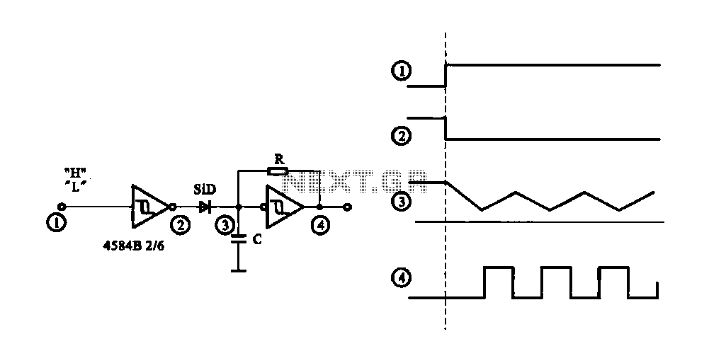
The circuit generates a controlled pulse signal. When a high pulse signal is applied to the input terminal O (start), the output pulse signal is activated. Conversely, when a low signal is received at the input terminal O (stop),...
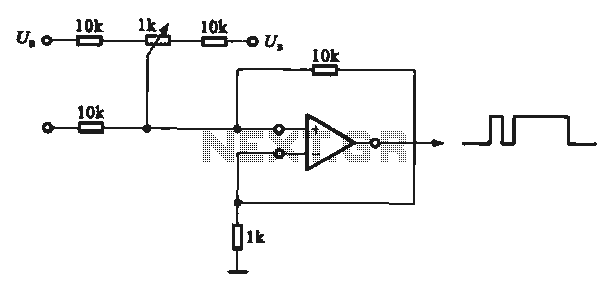
This circuit demonstrates the application of various types of pulse signal generating circuits using operational amplifiers. The circuit utilizes operational amplifiers (op-amps) to create different forms of pulse signals, which are essential in many electronic applications, including waveform generation, timing...
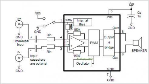
Stationary - MOPLL & Silicon Tuner TUA6020 2 Band TV Tuner Mixer-Oscillator-PLL with balanced IF-Amplifier. The TUA6020 device integrates a digitally programmable Phase Locked Loop (PLL) with a mixer-oscillator block that includes two balanced mixers and oscillators suitable for...
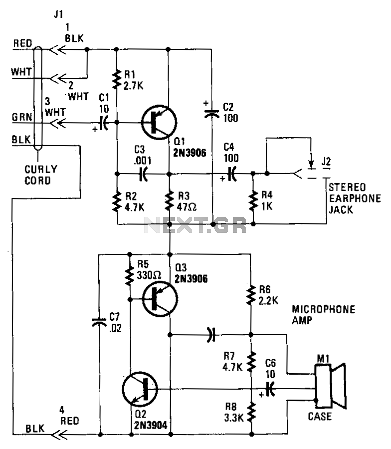
Transistor Q1 in the headset amplifier circuit amplifies the 30 mV signal intended for the earphones to 0.5 V, which is sufficient to drive stereo earphones. Capacitor C1 blocks any DC current from shorting back into the telephone base....
Tuning a system is typically a challenging task. The user must power the system, observe the spark length, shut it down, adjust the primary tap, restart, and repeat this process until the spark length is optimized. However, using a...
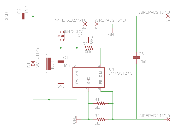
How would you like free boost driver designs? Although it is not possible to control anyone's actions, any individual interested in selling this circuit would be appreciated. The boost driver circuit is a type of DC-DC converter designed to step...
Warning: include(partials/cookie-banner.php): Failed to open stream: Permission denied in /var/www/html/nextgr/view-circuit.php on line 713
Warning: include(): Failed opening 'partials/cookie-banner.php' for inclusion (include_path='.:/usr/share/php') in /var/www/html/nextgr/view-circuit.php on line 713