
Free energy magnet motor
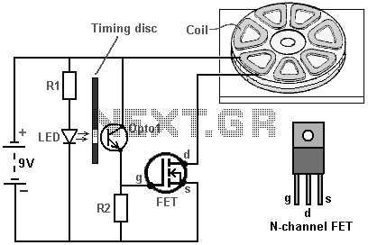
The described invention utilizes a magnetic motor design that incorporates three permanent magnets and a rotor-disc configuration to generate mechanical energy. The lower magnet serves as a stator, while the rotor, made from non-magnetic material, houses two additional magnets. This arrangement is complemented by a series of seven coils, which are strategically positioned to influence the magnetic fields during the rotor's movement. The activation of these coils is controlled by an infrared LED system that modulates the timing and duration of the magnetic interaction, enhancing the efficiency of energy conversion.
The magnetic interaction between the stator and rotor magnets is fundamental to the operation of this device. The unique arrangement of coils allows for a continuous rotational motion without manual initiation, facilitated by the staggered positioning of the rotor magnets and coils. When one of the rotor's magnets aligns with an inactive coil, the magnetic attraction is maintained, while the powered coil disrupts the magnetic link, creating torque that propels the rotor. This mechanism effectively prevents the rotor from locking into place, ensuring smooth operation.
The design's simplicity, combined with its ability to generate significant torque and energy output, positions it as a promising solution for applications requiring efficient energy conversion. The potential for scalability through the addition of more magnets further enhances its applicability in various energy generation scenarios.This invention relates to a method of producing useful energy with magnets as the driving force and represents an important improvement over known constructions and it is one which is simpler to construct, can be made to be self starting, is easier to adjust, and is less likely to get out of adjustment. The present construction is also relatively easy to control, is relatively stable and produces an amazing amount of output energy considering the source of driving energy that is used.
The present construction makes use of permanent magnets as the source of driving energy but shows a novel means of controlling the magnetic interaction or coupling between the magnet members and in a manner which is relatively rugged, produces a substantial amount of output energy and torque, and in a device capable of being used to generate substantial amounts of energy. This construction is relatively simple and yet the operation is powerful. The power is provided by three magnets, shown shaded in blue and yellow. The lower magnet is in the form of a disc with the poles arranged on the large, circular, flat faces.
This is the stator magnet which does not move. Positioned above it is a disc made of non-magnetic material (shaded in grey) and which has two magnets embedded in it. This disc is the rotor and is attached to the central vertical shaft. Normally, the rotor would not rotate, but between the two discs there is a ring of seven coils which are used to modify the magnetic fields and produce powerful rotation.
The powering up of these coils is very simple and it is arranged by shining a beam of Infra Red light from one of the Light-Emitting Diodes through a slot in an optical-timing disc attached to the rotating shaft. The LEDs and the photo-transistors are aligned with the centres of the seven coils. The position and width of the slot controls which photo-transistor gets switched on and for how long it remains powered up.
This is a very neat and compact arrangement. The really interesting part of the design is how the coils modify the magnetic fields to produce the output power of the device. The orientation of the magnet poles can be swapped over, provided that this is done for all three magnets.
Shown here is the situation when one of the rotor magnets has rotated to where it is above one of the coils which is not yet powered up. The South pole of the rotor magnet is attracted to the North pole which is the entire upper face of the stator magnet as shown by the three arrows.
If a voltage is applied to the coil, then this magnetic coupling is disrupted and altered. If any torque is developed as a result of the coil being powered up, then it will be developed to either side of the energised coil. If the coil is not powered up, then there will be full attraction between the magnets and no rotational force will be produced.
You will notice that there are two rotating magnets (an even number) and seven coils (an odd number) so when one of the rotor magnets is above a coil, then the other isnt. This staggering of the two positions is essential for generating smooth, continuous rotational torque and self-starting without any need to rotate the shaft manually.
This diagram shows a piece from both sides of the rotor disc, to explain the operation of the coils. On the left, magnet 56 overlaps coil 32 and coil 34. Coil 32 is powered up and this breaks the magnetic link on the left hand side of magnet 56. But, coil 34 is not powered up, so the attraction between magnet 56 and the disc magnet under the coils remains. Even though this attraction is at a downward angle, it creates a push on the rotor, driving it towards the right as shown by the red arrow.
While this is happening, the situation around the other side of the rotor disc is shown on the right. Here, magnet 54 is above coil 36 and that coil is not powered up, so there is no resulting drive in either direction.
The adjacent coil 38 is also not powered up and so has no effect on the rotation. This method of operation is very close to that of the motor design of Robert Adams described in the next chapter [see link below Ed]. It is important to understand that this method of operation is nothing like that of the John Bedini pulsers where the rotation of a disc is caused by the electrical pulse applied to a coil.
Instead, here, the coil acts as a magnetic shield, being provided with the minimum possible power to do its job. The coil is, in effect, a shield which has no moving parts, and so is a very clever mechanism for overcoming the tendency for the rotor magnets locking on to the stator magnets and preventing rotation.
At any moment, six of the seven coils are inactive, so in effect, just one coil is powered. This is not a major current drain. It is important to understand that the power of this motor is provided by the permanent magnets pulling towards each other. Each of the two magnets applies a horizontal pull on the rotor every seventh of a turn, that is, every 51.1 degrees in the rotation.
As the coils are an uneven number, the rotor gets a magnetic pull every 25.5 degrees in the rotation, first from one rotor magnet and then from the other rotor magnet. It follows then, that the power of the motor can be increased by adding more magnets. The first step in this search for additional power is to add a second disc magnet and coils on the other side of the rotor, so that there is a second pull on the magnet.
🔗 External reference
Related Circuits
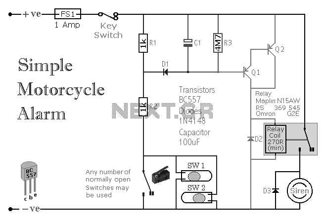
A simple transistor-based motorcycle alarm circuit. This circuit is easy to build and designed to operate at 12 volts. However, by replacing the relay with one that has a 6-volt coil, it can also provide protection at that voltage. The...
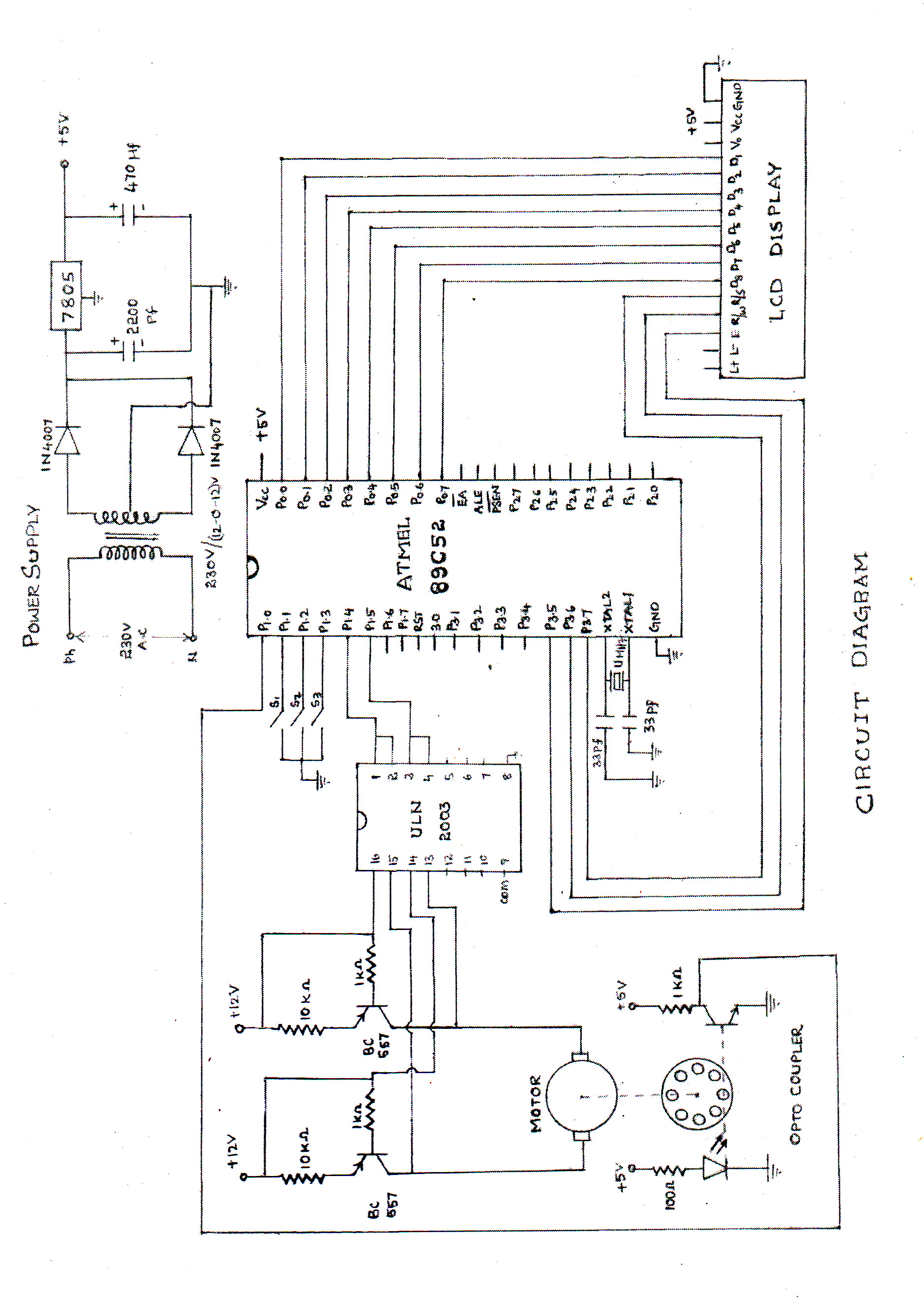
The speed of the DC motor is controlled using an ATMEL89C52 microcontroller, with feedback provided by an optocoupler. The circuit diagram can be viewed above (click on the diagram for a larger view). The motor speed is regulated by...
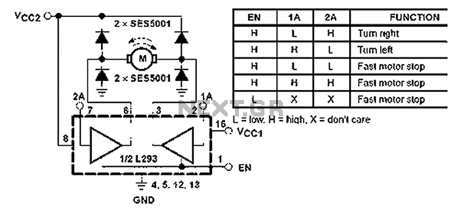
All inputs are compatible with TTL. Each output consists of a complete totem pole driver circuit, utilizing Darlington transistors and pseudo-Darlington sources. The driver enable signals, labeled as 1,2 EN and 3,4 EN, control the activation of drivers 1...
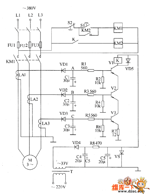
The motor protection circuit consists of a power supply circuit, a current detection circuit, and a protection control circuit, as depicted in the accompanying diagram. The power circuit includes a power transformer (T), a rectifier diode (VD4), filter capacitors...
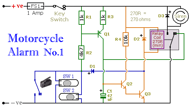
When one of the normally-open switches is closed, two actions occur. First, the negative side of the relay coil connects to ground through D1, energizing the relay, which in turn activates the siren. Second, the emitter-base junction of Q1...
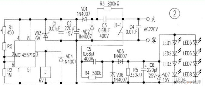
The circuit is depicted in Figure 1, while the electrical schematic diagram is presented in Figure 2. The AC voltage of 220V is reduced by components C3 and R3. The diodes VD1 and VD2 rectify the voltage, and capacitors...