
Motor protector circuit diagram 8
The motor protection circuit is designed to safeguard motors from various electrical faults, ensuring reliable operation and longevity. The power supply circuit plays a crucial role in providing stable voltage and current to the entire system. The power transformer (T) steps down the input voltage to a suitable level for the circuit's operation. The rectifier diode (VD4) converts the alternating current (AC) output from the transformer into direct current (DC). Following this, the filter capacitors (C4 and C5) smooth out the rectified DC voltage, reducing ripple and providing a stable power source.
The current detection circuit is essential for monitoring the motor's operating conditions. It typically incorporates a current sensing element, such as a shunt resistor or a Hall effect sensor, to measure the current flowing to the motor. This information is fed into the protection control circuit, which evaluates the current levels against predefined thresholds. If an overcurrent condition is detected, the protection control circuit activates protective measures, such as disconnecting the motor from the power supply to prevent damage.
The current limiting resistor (R8) is included in the power circuit to manage inrush currents during motor startup, ensuring that the initial current draw does not exceed safe levels. The Zener diode (VS) serves as a voltage clamp, protecting sensitive components from voltage spikes that may occur during operation.
In summary, the motor protection circuit integrates these components to create a robust system that not only supplies power to the motor but also actively monitors its operational parameters to prevent damage due to electrical faults. The design emphasizes reliability and safety, making it suitable for various industrial and commercial applications.The motor protection circuit is composed of power supply circuit, current detection circuit and protection control circuit, the circuit is shown as the chart. Power circuit is composed of the power transformer T, rectifier diode VD4, filter capacitors C4, C5, current limiting resistor R8 and Zener diode VS and other components, the circuit is used to generat..
🔗 External reference
Related Circuits
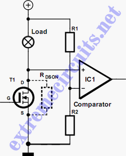
In applications where a MOSFET is used to switch a load, it is relatively straightforward to incorporate short-circuit or overload protection. This can be achieved by utilizing the internal resistance RDS(ON), which generates a voltage drop proportional to the...
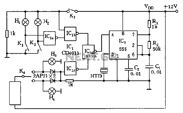
The circuit presented is a 555 timer-based alarm system for vehicles, which primarily consists of a 555 timer and a quad 2-input NAND gate configuration. It is designed to produce a long beep sound when oil pressure is low...
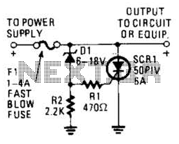
Many modern devices have shutdown circuits that are designed to remove power from the device when the voltage rises above a predetermined threshold. This circuit blows a fuse to protect the device under power. Shutdown circuits are critical components in...
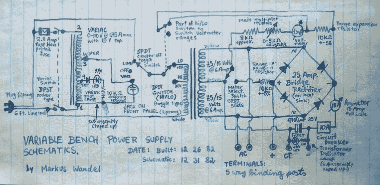
This power supply is able to deliver adjustable center-tapped DC from 0 to about 30 volts, as well as AC directly from the Variac and from the main transformer before the rectifier. What's primitive by today's standard is that...
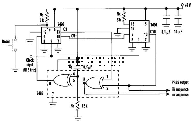
In this circuit, an additional exclusive-OR gate is connected after the modulo-2 feedback, with CI and R2 applying the supply turn-on ramp into the feedback loop. This provides sufficient transient signal so that the PRBS generator can self-start during...
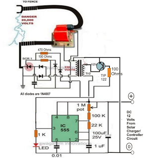
A fence charger or energizer is a device used to electrify a fence or boundary to protect the premises from human or animal intrusions. These boundaries are often located in large fields and parks, typically away from urban areas,...