
speed control of dc motor
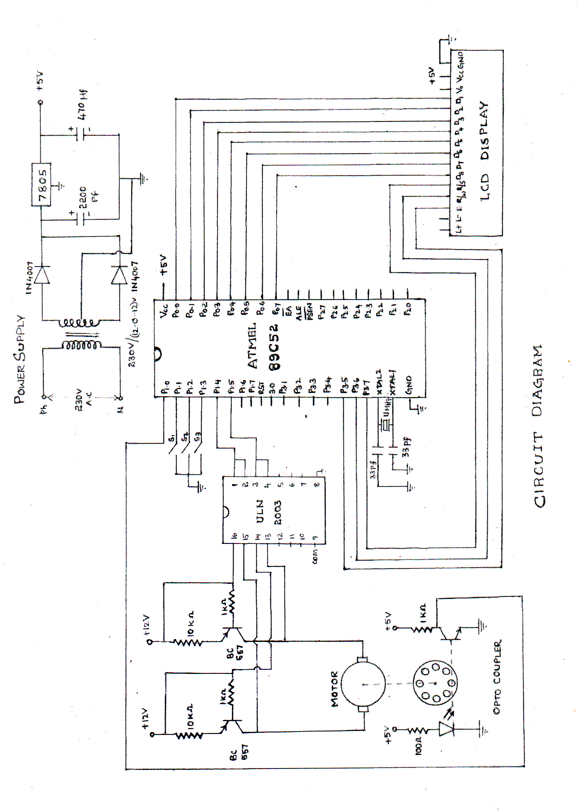
The circuit described utilizes an ATMEL89C52 microcontroller to manage the speed of a DC motor through pulse width modulation (PWM). This method allows for efficient control of the motor's speed by adjusting the average voltage supplied to the motor. The microcontroller generates a PWM signal, which is fed into a transistor acting as a switch. The transistor is configured to operate in saturation and cutoff regions, enabling it to turn on and off rapidly.
An optocoupler is employed in this circuit to provide feedback from the motor. The optocoupler isolates the microcontroller from the motor circuit, ensuring that any voltage spikes or noise generated by the motor do not affect the microcontroller's operation. The feedback signal from the optocoupler allows the microcontroller to monitor the actual speed of the motor, facilitating closed-loop control.
By varying the duty cycle of the PWM signal, the average voltage applied to the motor can be adjusted, thereby controlling its speed. A higher duty cycle results in more power delivered to the motor, increasing its speed, while a lower duty cycle decreases the power and slows the motor down. This method is efficient and allows for precise control of motor speed.
The schematic diagram associated with this circuit illustrates the connections between the microcontroller, transistor, optocoupler, and the DC motor. It is essential to ensure that the components are rated appropriately for the motor's voltage and current requirements to prevent damage. Additionally, proper heat sinking should be considered for the transistor if high currents are involved.speed of the d.c. motor is controlled by using ATMEL89C52 lmicrocontroller ,feedback from optocoupler. the circuit diagram can be seen above(click on the diagram to get larger view) the motor speed is controlled by the use of transistor as control switch varying the dutycycle of the switching signal to the transistor varies the power of.. 🔗 External reference
Related Circuits
Upon entering the password, the application, in this case "LED," will illuminate. In this digital locking system project, the interfacing of a keypad and a 16x2 LCD with a microcontroller will be explored, along with the accompanying code. This...
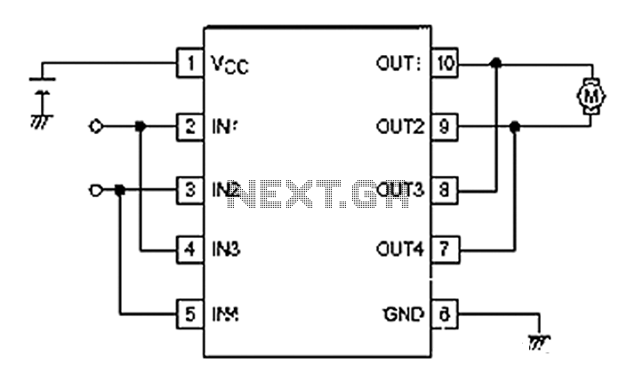
A simple motor control project for forward and backward drive can be implemented using the LB1948M motor driver IC, which features two channels for motor control. The LB1948M is an ideal choice for 12V motor drive systems and can...
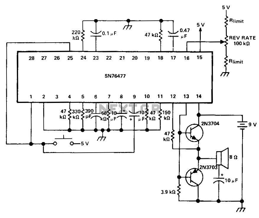
For two simultaneous race-car sounds. The mixer can be multiplexed between the SLF and VCO functions. The circuit design involves a sound synthesis system capable of generating two distinct race-car sounds concurrently. This is achieved through a mixer that facilitates...
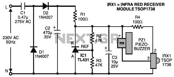
The remote control tester circuit is a simple and easy-to-construct device for verifying the basic operations of an infrared remote control unit. It is low-cost and designed around infrared technology. The remote control tester circuit typically consists of a photodiode...
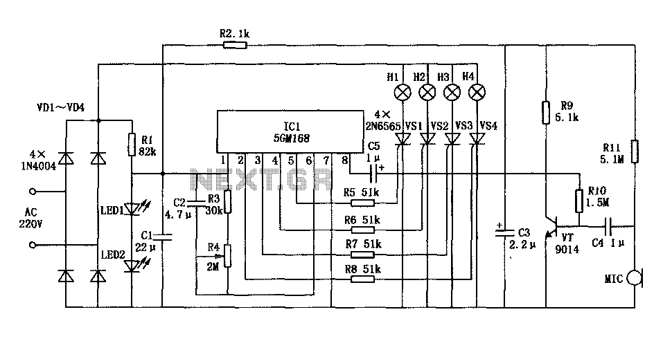
Family karaoke lighting design incorporates various methods for circuit control. The control circuit described here features a four-way light output with loop jumping and speed control capabilities. A microphone detects the acoustic signal strength, allowing the lights to jump...
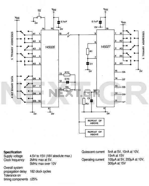
This encoder can generate up to 19,683 codes from 9 address lines by detecting 1, 0, or an open circuit. To initiate the transmit sequence, pin 14 should be pulsed low. The encoder will output a data stream on...