
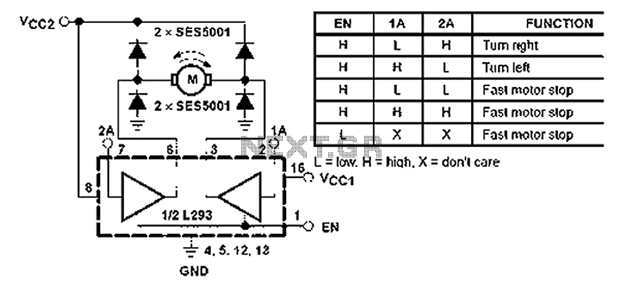
L293 reversible motor drive circuit diagram
The described circuit employs TTL-compatible inputs and outputs, ensuring seamless integration with various digital logic systems. The totem pole configuration allows for efficient driving of loads, maximizing current delivery while maintaining low output impedance when active. The use of Darlington transistors enhances the current gain, enabling the circuit to control larger loads without excessive input current.
The enable signals (1,2 EN and 3,4 EN) play a critical role in managing the operation of the drivers. By applying a high signal to these inputs, the corresponding drivers are activated, allowing current to flow through the outputs. This feature is essential for applications requiring precise control over motor direction and operation, as it enables users to switch between forward and reverse motion by appropriately toggling the enable signals.
The L293 and L293D integrated circuits are specifically designed to handle inductive loads, which are common in motor control applications. The L293 can handle a continuous current of 1 A per channel, making it suitable for larger motors or multiple smaller motors. The L293D, with its lower current rating of 600 mA, is ideal for smaller applications or where space is a constraint. Both chips include built-in diodes for flyback protection, which safeguard the circuit from voltage spikes generated when inductive loads are switched off.
This configuration allows for the implementation of H-bridge circuits, which can control the direction of a motor by reversing the polarity of the voltage applied to its terminals. This capability is essential for applications such as robotics, where precise control over movement is required. The ability to place the outputs in a high impedance state when the drivers are disabled further enhances the versatility of the circuit, allowing for safe and efficient operation without risking damage to the components.
In summary, the combination of TTL compatibility, totem pole driver circuits, and the use of L293 and L293D integrated circuits provides a robust solution for controlling motors and solenoids in a variety of electronic applications. The detailed operation of the enable signals and the characteristics of the driver outputs ensure that this circuit can effectively manage the demands of high-current applications while maintaining reliability and efficiency.All input is compatible with TTL. Each output is a complete totem pole driver circuit, Darlington transistors chip and pseudo-Darling source. Driver enable, 1,2 EN and drivers 3 and 4 by a 3,4 EN Enable Enable drives 1 and 2. When the enable input is high, the associated driver is enabled, the output active in the input stage with them. When the enable input is low, these drivers are disabled, and the output is closed, in a high impedance state.
With the right data entry, each driver to form a complete H (or bridge) for reversible drive motor or solenoid applications. High current L293 quadruple half - driving integrated circuit H, we can design a very simple high-efficiency motor control L293 is designed to provide a voltage bidirectional drive current of 1 A 4.V to 3V is designed to provide the L293D bidirectional drive current 600 mA voltage from 4.V to 36 V.
both devices are designed to drive inductive loads, such as relays, solenoids, DC and bipolar stepper motors, and other high-current/high positive supply load voltage applications. All input is compatible with TTL. Each output is a complete totem pole driver circuit, Darlington transistors chip and pseudo-Darling source.
Driver enable, 1,2 EN and drivers 3 and 4 by a 3,4 EN Enable Enable drives 1 and 2. When the enable input is high, the associated driver is enabled, the output active in the input stage with them. When the enable input is low, these drivers are disabled, and the output is closed, in a high impedance state.
With the right data entry, each driver to form a complete H (or bridge) for reversible drive motor or solenoid applications.
Related Circuits
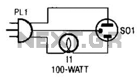
The tester provides an audible indication of the logic level of the signal presented to its input. A logic high is indicated by a high tone, a logic low is indicated by a low tone, and oscillation is indicated...
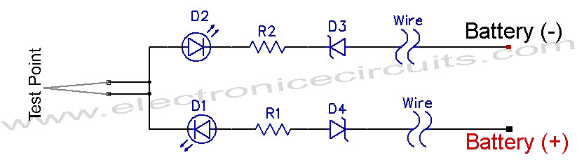
12V Vehicle Electrical Wiring Tester Circuit. This tester is useful for checking vehicle electrical circuits. Two LEDs indicate whether the circuit is live or not. The 12V vehicle electrical wiring tester circuit is designed to provide a simple yet effective...
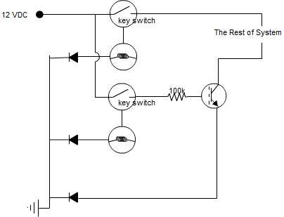
A circuit is being designed that incorporates two key switches, which must both be closed for current to flow through the circuit. The proposed circuit configuration employs two key switches connected in series. In this arrangement, the current can only...
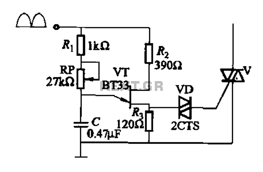
Figure 16-29 (a) illustrates the trigger output through a resistor R2, while Figure 16-29 (b) depicts the integration of a programmable unidirectional transistor (PUT) trigger circuit. The adjustable potentiometer RP can modify the conduction angle of the TRIAC to...
This remote telephone bell ringer enables the use of a large and loud external bell instead of or in addition to the built-in ringer found in most modern telephones. It is particularly suitable for large outdoor areas, noisy shops,...
The circuit utilizes the LM324 low-power operational amplifier, which consumes approximately 3mA of current. This low current draw ensures that the battery will not be adversely affected if the circuit remains connected for extended durations. The LM324 is a quad...