
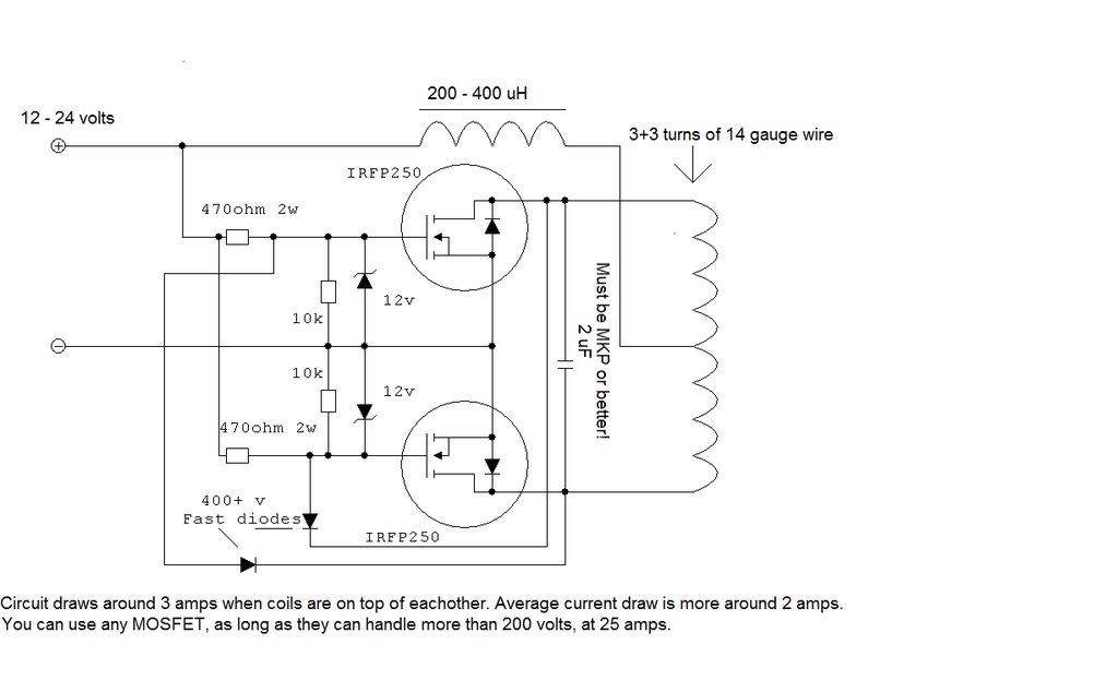
Free Energy Schematic
The circuit design for this concept typically includes several key components. The high-frequency source can be generated using an oscillator circuit, which may utilize a crystal oscillator or a high-speed transistor-based oscillator to achieve the desired frequency. The output of this oscillator is directed to a rectifier circuit, which can be constructed using diodes capable of handling high voltage and fast switching speeds, such as Schottky diodes. This rectification process converts the alternating current (AC) signal into direct current (DC), allowing for efficient charging of the capacitors.
The bank of capacitors is selected based on the required capacitance and voltage ratings, ensuring they can handle the high-voltage charge without risk of breakdown. Capacitors such as tantalum or ceramic types may be suitable due to their ability to maintain stability under high-frequency conditions.
For the discharge phase, a high-speed electronic switching circuit is critical. This can be achieved using MOSFETs or IGBTs (Insulated Gate Bipolar Transistors), which are capable of switching on and off at very high speeds, allowing for precise control over the discharge timing. The discharge circuit is designed to release the stored energy from the capacitors in short, controlled pulses, which can be utilized for various applications, such as in pulsed power systems or high-energy physics experiments.
To ensure that the high-voltage charge flows in one direction only, a unidirectional rectification method is employed. This can be achieved through the use of a bridge rectifier configuration or by implementing a combination of diodes in series with the capacitors.
Overall, this circuit design encapsulates a sophisticated approach to managing high-frequency, high-voltage signals for energy storage and rapid discharge applications, emphasizing the importance of component selection and circuit configuration to achieve optimal performance.The basic concept as I understand it, is a high frequency high voltage low current rectified and then used to charge a bank of high value capacitors and then to discharge them in pulse mode for brief period of time, nano seconds in fact by, means of a high speed electronic switching circuit or mechanical device and a rectification method that will only allow the high voltage charge to flow in one direction. 🔗 External reference
Related Circuits
In this circuit, a 74HC14 hex Schmitt trigger inverter is used as a square wave oscillator to drive a small signal transistor in a class C amplifier configuration. The oscillator frequency can be either fixed by a crystal or...
This power supply circuit operates using 120 volts from household mains and should only be undertaken by individuals with the appropriate knowledge and skills to safely construct such a project. Failure to do so may result in personal injury...
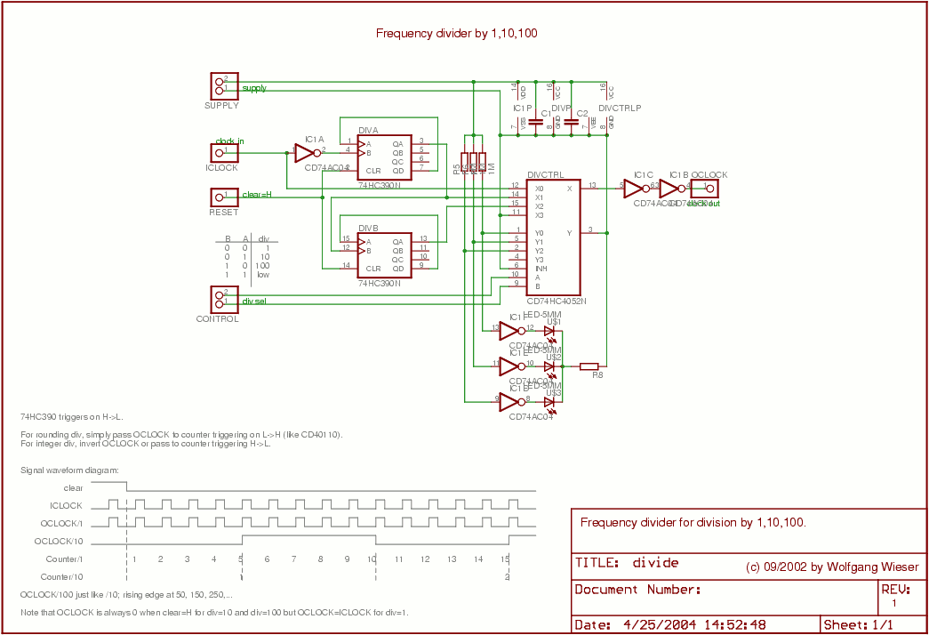
The divider design is straightforward. Users can select a division factor of 1, 10, or 100, or opt for no output (tied low) through the CONTROL input connected to the analog multiplexer HC4052. The design utilizes AC04 to drive...
The design primarily consists of the ATmega328P-PU microcontroller and an LCD display. Both components necessitate a stable power supply. The ATmega328P-PU microcontroller is an 8-bit AVR microcontroller that operates at a clock speed of up to 20 MHz. It features...
To construct the circuit, follow the provided schematic. If assistance is required, do not hesitate to reach out for support. If there are difficulties in identifying the components... To build the circuit effectively, it is essential to adhere closely to...
Protect your valuable laptop against theft using this miniature alarm generator. Fixed inside the laptop case, it will sound a loud alarm when someone tries to take the laptop. This highly sensitive circuit uses a homemade tilt switch to...