
Comments on the Circuits of the first Transistor Radios
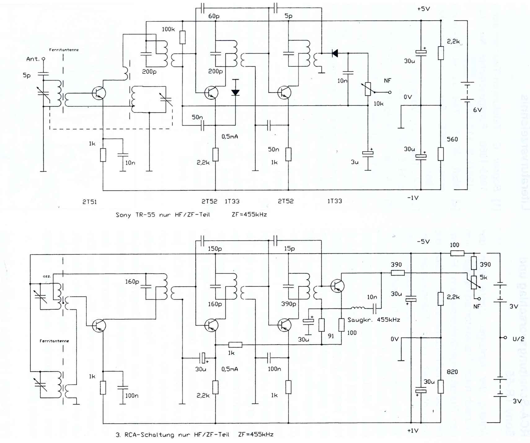
At the beginning of the 1950s, interest in transistor radios did not originate from broadcasting equipment manufacturers but rather from semiconductor manufacturers eager to showcase the utility of their transistors and explore new applications. The Radio Corporation of America (RCA), in conjunction with Telefunken, both semiconductor and broadcasting equipment manufacturers, conducted extensive research. RCA unveiled its first small experimental transistor radio in November 1952, along with ten other developmental devices, followed by another in the summer of 1953 and a third experimental device in early 1954, which was pocket-sized. The circuit diagrams for the latter two devices were also published. A comparison of the circuit of the third RCA unit with the Sony TR-55 from August 1955 highlights RCA's influence on the RF and IF stages. By utilizing a modified control circuit, the active rectifier was replaced with a germanium diode. The rearrangement of the oscillator, the first IF, and the input circuit was dictated solely by the grounding of the variable capacitor housing.
The schematic representation of the "Telefunken TR-1" and the "Regency TR-1" reveals their similarities, showcasing the evolution of circuit designs during this pivotal time in electronics. The Regency TR-1's innovative features, particularly its self-oscillating mixer and unique supply voltage, were significant advancements in the field of portable radio technology. The adaptations made by the Telefunken TR-1 reflect the challenges and limitations faced by manufacturers in utilizing available components while striving to achieve comparable performance levels. The historical context of transistor radio development underscores the collaborative efforts of semiconductor and broadcasting companies to push the boundaries of radio technology, ultimately leading to the widespread adoption of transistor radios in consumer markets.The circuitry of the Regency shows some peculiarities. The circuit of the self-oscillating mixer stage, the base bias voltage of the second IF stage from the AF power stage, the unusual IF of 262KHz and the supply voltage of 22. 5 V are all characteristic of the device. Other experimental circuits of the time, as well as the upcoming transistor receivers from 1955 below, deviate from its circuit design
significantly. A great similarity is apparent when comparing the circuit of the "Telefunken TR-1" with the "Regency TR-1" (Fig. 1). After the initial pioneering work in the semiconductor factory at Ulm, it is clear that the Hanover factory became active only after the release of Regency receiver.
It could be thought of as follows (but unfortunately there are no relevant authorities):They adapted the Regency`s circuit to their available transistors. Because these were pnp types, the supply voltage needed to be reversed. Also since they had poorer RF characteristics, the IF stages were increased to three and the self-oscillating mixer was replaced by separate mixer and oscillator stages.
This was necessary to reduce the mixer transistor noise factor. The intermediate frequency was virtually the same. Of course, the RC components to neutralize the IF stages had to be changed. Moreover, they used the same components values, where possible. (There were, however, scarcely any alternatives. ) The speaker was similar to the Jensen model used in the Regency. The claim that the development and manufacture of the Telefunken TR-1 took place in the summer of 1954 (3), is probably questionable. Whether a pocket portable was seen behind closed doors at the Hannover Fair in March 1955, is yet to be determined (4).
A Regency TR-1 (with Intermetall transistors) would be shown at the DG sseldorf Radio Exhibition in 1955 by Intermetall (6). Figure 1: Circuit of the "Telefunken TR-1" dated August 55 (top) compared to the "Regency TR-1" from November 54 (bottom).
The similarities are obvious. (click on image for full scale schematic) At the beginning of the Fifties interest in Transistor radios did not come from the broadcasting equipment manufacturers. It was the semiconductor manufacturers who wanted to demonstrate the usefulness of their transistors and expand their applications.
In particular the Radio Corporation of America (along with Telefunken, both semiconductor and broadcasting equipment manufacturers) had carried out substantial research. RCA showed its first small experimental transistor radio in November 1952 (!), in addition to ten other developmental devices, another in the Summer of 1953 and a third experimental device on or before January 1954.
The latter in pocket format. The circuit diagrams of the latter two devices were also published. A comparison of the circuit of the third RCA unit with the Sony TR-55 from August 1955 shows the RCA influence in the RF and IF stages. Using a modified control circuit they replaced the active rectifier with a germanium diode. The altered arrangement of the oscillator, the first IF and the input circuit is determined solely by the fact that the housing of the variable capacitor (the rotors) was grounded (Fig.
2). [4] o. A. :Radio Mentor H. 6, 1955, p 299: Editorial "Something really new for the Europe was in the air in Hanover but not even demonstrated: Transistor pocket sets and transistor automotive radios. (ie Radio Mentor suggests that these could be seen unofficially!) [5] Dr. Rost: Kristalloden-Technik. 2. Aufl. , p 417ff. : VolI-Transistor- Mittelwellen-Super. Verlag von Wilhelm Ernst & Sohn, Berlin[6] o. A. : Bericht G ber die Funkausstellung DG sse 🔗 External reference
Related Circuits
A radio that has been stored for years on a dusty shelf needs to be gently revived to restore its reliable operation and provide warm, pleasant sounds for years to come. Here are a few general notes on how...
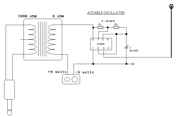
Two ICM7555 CMOS 555 timers are available, and there is an inquiry about effective AM radio transmitter circuits that utilize one or both of these timers. The ICM7555 is a low-power CMOS version of the classic 555 timer, which can...
This single transistor audio mixer is utilized in an amplifier circuit design featuring a base-driven transistor, where the emitter is current-controlled. The majority of the driving current flows through the collector. This audio mixer circuit employs a single transistor to...
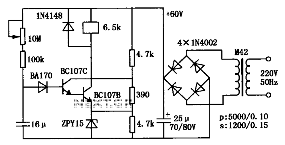
The circuit is a relay delay pull transistor configuration. Initially, when powered, the 16 µF capacitor has a voltage of zero, resulting in both transistors being off, and the relay remains inactive. As the 16 µF capacitor charges over...
The Wien-Bridge oscillator meets specific requirements due to the presence of a low-pass filter, a high-pass filter, and a 180-degree phase shift from the feedback networks connecting the input to the output. This configuration results in a total phase...
This oscillator utilizes a significant capacitance-to-inductance ratio. L1 is a one-turn coil made from a loop of #12 wire, measuring 12 inches in diameter. This circuit is advantageous for applications such as metal detectors, where a loop antenna is...
Warning: include(partials/cookie-banner.php): Failed to open stream: Permission denied in /var/www/html/nextgr/view-circuit.php on line 713
Warning: include(): Failed opening 'partials/cookie-banner.php' for inclusion (include_path='.:/usr/share/php') in /var/www/html/nextgr/view-circuit.php on line 713