
frequency counter

This problem can be avoided by using a synchronous counter instead. In this circuit, the rate of an extra count depends only on a fractional number of less than 1, meaning the clock duty ratio does not affect the extra count. However, the synchronous counter can encounter abnormal operation due to asynchronous input that does not guarantee setup and hold times. To avoid this problem, precautions, such as separating counter stages to insulate most synchronous blocks or synchronizing control signals with the clock to prevent errors, should be taken. A frequency measurement system realized in a digital counting circuit is typically referred to as a "Frequency Counter."
The described frequency counter project features a digital architecture that allows for the measurement of frequency, pulse width, and pulse period. The core of the design utilizes an AT90S8515 microcontroller, which handles the counting, displaying, and communication functions effectively. The circuit can be expanded using additional microcontrollers if required, providing flexibility for different applications.
The frequency measurement process is based on counting the number of cycles of an input signal over a defined period. This method is straightforward and relies on the principle of digital counting, where the input signal is fed into a counter IC that tallies the cycles. The project also addresses the limitations of conventional counting methods, particularly at low frequencies, by implementing a longer gate time for improved resolution.
One critical aspect of this design is the use of a synchronous counter to mitigate the issues associated with extra counts caused by clock duty ratios. This ensures that the frequency readings are accurate and reliable, particularly in scenarios where the input frequency is close to the counting threshold. The design emphasizes proper synchronization and isolation of counter stages to prevent erroneous readings due to asynchronous inputs.
Overall, this universal counter project represents a versatile and practical solution for frequency measurement, suitable for both hobbyists and more advanced applications in electronics. The inclusion of additional measurement capabilities beyond simple frequency counting enhances its utility in various electronic projects.The frequency counter is the most popular instrument in the home maid instruments. I think that the reason why it is built widely is: it can be built easily because it is digital circuit, it is generic measurement and many construction kits are available. Many electronics hobbyists will experienced to build any frequency counter. This project is second trial for me. But building two ordinaly frequency counter is not smart so that some additional functions ware impremented to the frequency counter.
The function is not that abundant compared to generic universal counter however it can measure pulse period/width besides frequency, I named this project "Universal Counter". The Frequency means number of electrical or mechanical vibration cycles per unit time, to explain this might not be needed now... Hz (hertz) is used for a unit of the frequency and is defined as an SI unit, and it means number of cycles per second: e.g.
when 100 cycles are counted per a second, it is 100 Hz. Formarly c/s was used for unit of the frequency. When count number of cycles of the input signal for one second, the value of frequency can be got in the counter. This can be realized by simple counter circuit so that this was the conventional frequency measureing method.
Many counter IC have been released and many frequency counters thak work in this method are being shipped now. An AT90S8515 is used for the controller because it is very easy to use. The control process are conting, displaying and communicating mainly. They are not that complex, any other microcontroller, such as 8051, H8 and 78K, will able to be used instead.
This is the simplest method but the measureing resolution is limited at low frequency. To ensure more resolution, the gate time must be expanded: e.g. when measure at resolution of 1 mHz, 1000 seconds is needed to measure one time. Every measureing method needs to control any clock signal. However using an AND gate that shown in the diagram of principle will occure an extra count. The error rate depands on the duty ratio of the clock signal: e.g. simmetrical clock signal occures +0.5 counts average. This cannot be ignored according to circumstance. At high frequency of several MHz, this will not affect measureing accuracy, however input signal of 99.7Hz results 100 or 101 Hz is not good. This problem can be avoided by using a synchronous counter instead. In this circuit, the rate of an extra count depends on only fractional number of less than 1, the clock duty ratio doesn't affect to the extra count.
However the synchronous counter can occure any abnormal operation due to asynchronous input that is not guaranteed ts and th. To avoid this problem, any care, such as separating counter stages to insurate most synchronous block or synchronizing control signals with clock to avoid that error, should be taken on this point.
A frequency measurement system which is especially realized in digital counting circuit seems being called "Frequency Counter". 🔗 External reference
Related Circuits
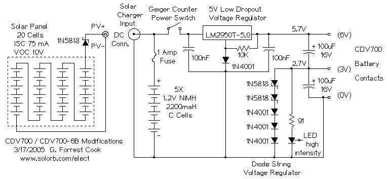
This project involves making several modifications to an early 1960s era Victoreen CDV700 or CDV600-6B geiger counter. These counters are available on E-Bay for around $50 to $100. The modifications use modern electronic parts to improve the counter's stability,...
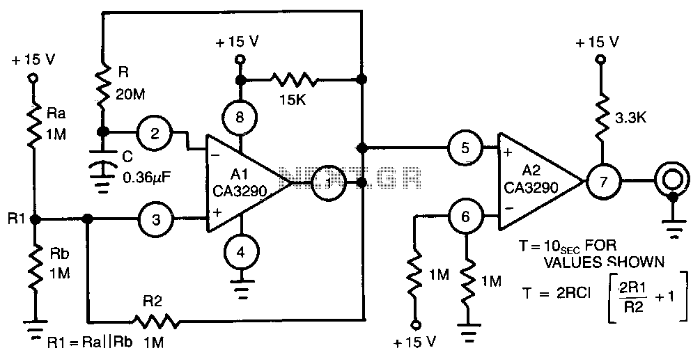
This circuit utilizes one half of the CA3290 BiMOS dual voltage comparator as a conventional multivibrator. The second half ensures frequency stability against the effects of output loading. Large values of the timing resistor, Rl, guarantee long time delays...
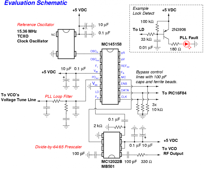
The Motorola MC145158 is a dual-modulus, serial-input PLL frequency synthesizer commonly utilized in older Motorola cellular phones. For detailed technical specifications, refer to the MC145158 datasheet. Although the MC145158 is no longer in production, it can occasionally be found...
The circuit illustrated is a straightforward digital frequency meter that displays the frequency in hertz of an astable 555 timer. It may potentially be modified for alternative applications. An NPN transistor, TR2, is linked to the 555 astable timer...
The heart of the lock is the 40022 octal counter. When first powered C2 is charged via R5 so the reset input of the counter is kept high. That causes output Q to go high while all the other...
This circuit utilizes a synthesized sound chip from Holtek, the HT-2811, which produces the sound of a "ding-dong" chiming doorbell. Additionally, it incorporates a CMOS 4026 counter display driver integrated circuit (IC) to tally the number of visitors. The...