
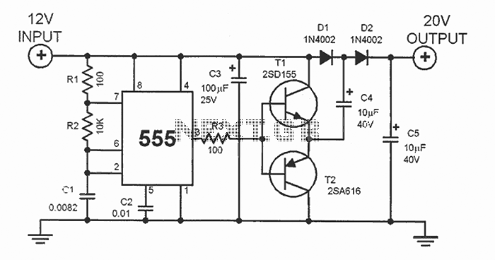
555 ASTABLE_FREQUENCY METER
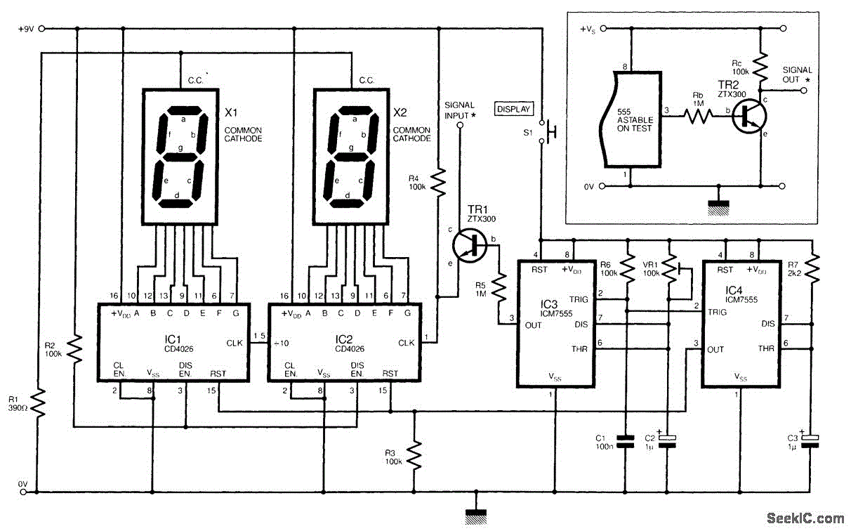
This digital frequency meter circuit employs a 555 timer in astable mode, which generates a continuous square wave output. The frequency of this output can be measured and displayed using the accompanying circuitry. The primary components include two NPN transistors, TR1 and TR2, which play crucial roles in signal amplification and processing.
Transistor TR2 is directly connected to the output of the 555 timer. It serves to buffer the signal and provide necessary isolation from the timer circuit. The output from TR2 is then fed into the collector of TR1, which is configured as a switch. When the output from TR2 exceeds a certain threshold, TR1 activates, allowing current to flow through the main circuit, which may include a digital display module or a frequency counter.
The frequency meter's design can be adapted for various applications beyond measuring the frequency of a 555 timer. For instance, with appropriate modifications, it can be used to measure other digital signals or even analog signals converted to a digital format. The output signal's characteristics can be tailored by adjusting the resistor and capacitor values in the 555 timer circuit, thereby changing the frequency range of the meter.
Additionally, the circuit can be enhanced with features such as a calibration mechanism, allowing for accurate frequency readings across a wider range. Implementing a microcontroller could also facilitate more advanced functionalities, such as data logging or interfacing with other digital systems for automated frequency measurement tasks.
Overall, this digital frequency meter circuit provides a versatile platform for frequency measurement, with the potential for various modifications and enhancements to suit specific requirements.The circuit shown is a simple digital frequency meter, which indicates the frequency in hertz of an astable 555 timer. It could, perhaps, be adapted for other uses. An NPN transistor, TR2, is connected to the 555 astable to be measured, as shown in the in-set, and the output signal obtained is hooked to the main circuit via transistor TR1 collector (c)..
🔗 External reference
Related Circuits
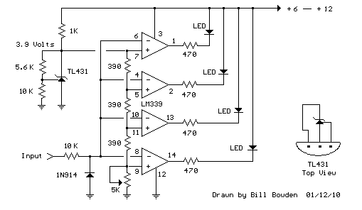
This circuit functions similarly to the previous one and features a 4 LED bar graph that displays the voltage of a common 3.6-volt lithium-ion rechargeable cell phone battery. The reference voltage is supplied by a TL431 programmable voltage source,...
A simple metal detector circuit can be implemented using a 555 timer chip. The schematic diagram illustrates that this project requires only a few external electronic components. The metal detector circuit utilizing a 555 timer operates in astable mode, generating...
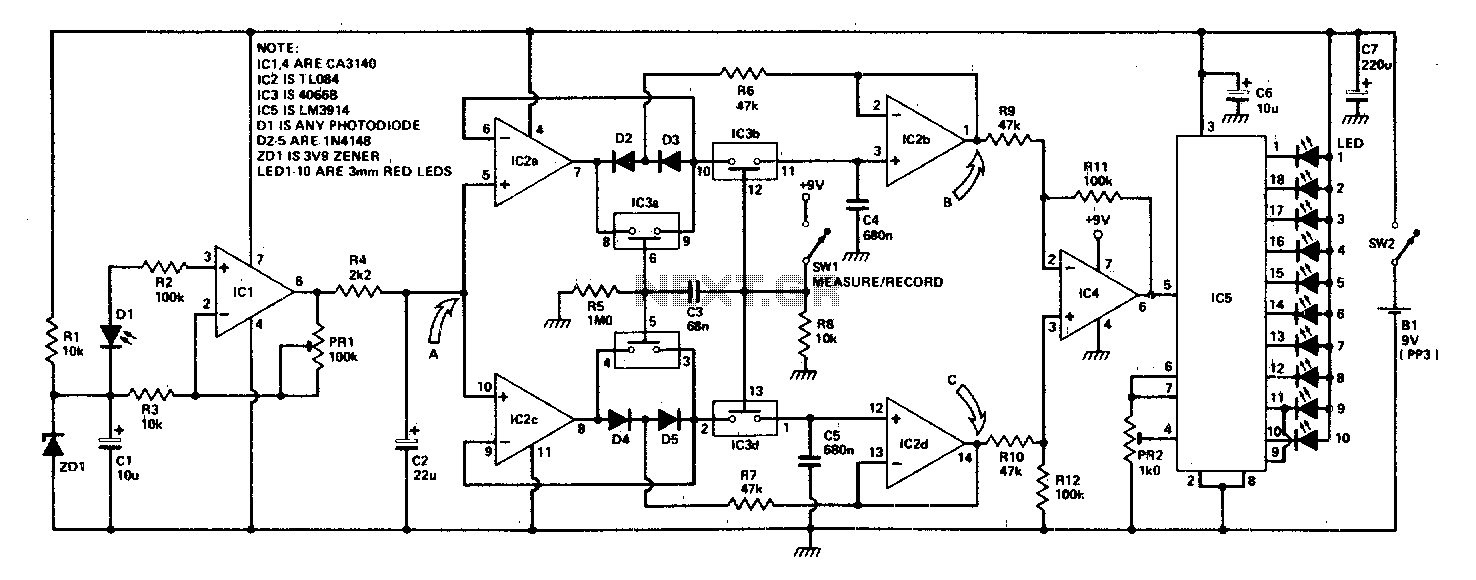
The circuit arrangement includes a photo-amplifier that converts varying light levels in an enlarger into a voltage signal. This signal is processed by two peak detectors: one tracking the peak positive voltage and the other tracking the peak negative...
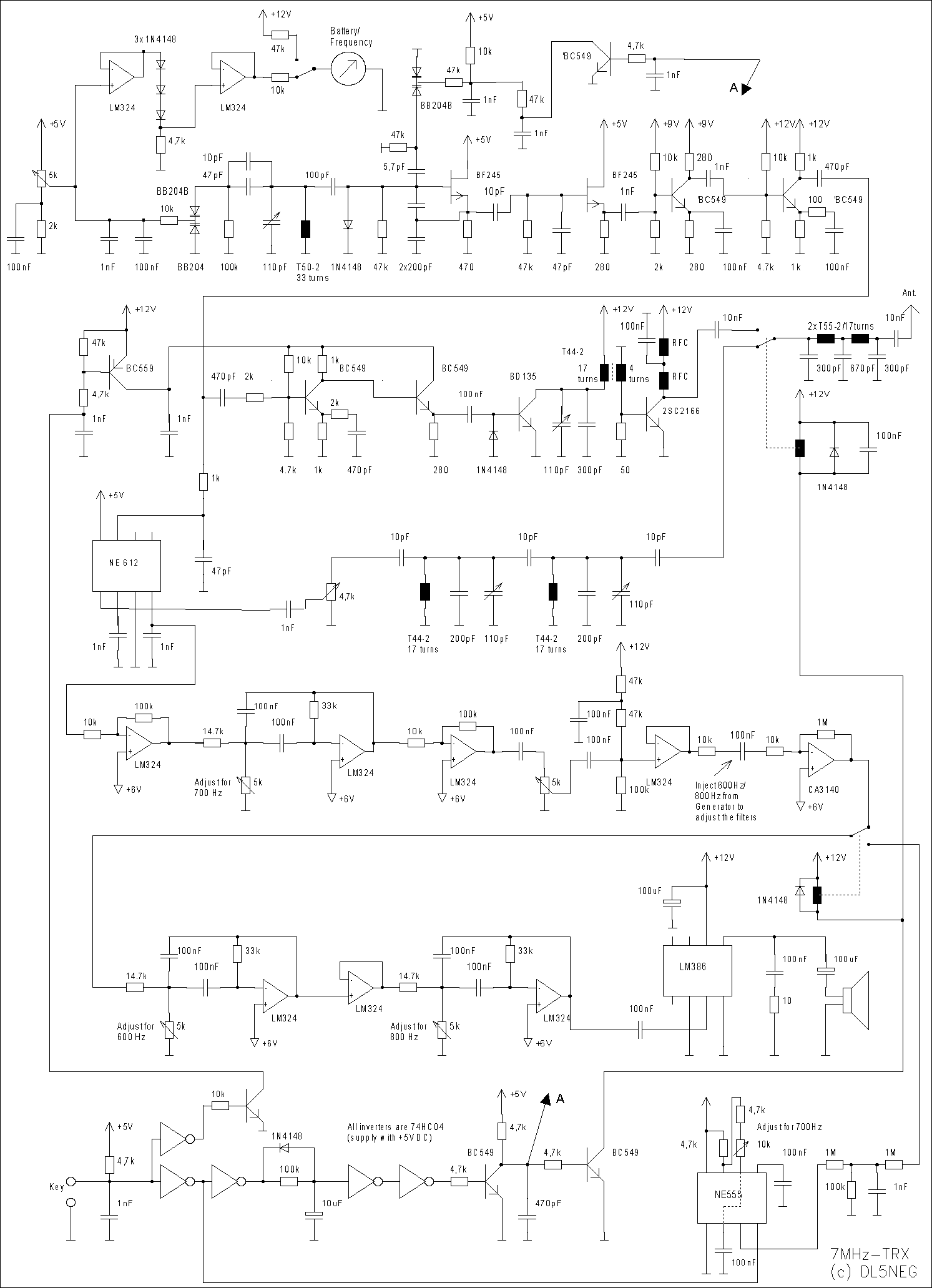
This was one of my very first transceiver developments. This page was also one of the very first circuit descriptions that I put on the internet quite some years ago. Today I would not build a transceiver like I...
This DC voltage doubler circuit generates a voltage that is double the input supply voltage. It is beneficial when a higher voltage is required from a single lower voltage power source, particularly in applications with low current consumption. The DC...
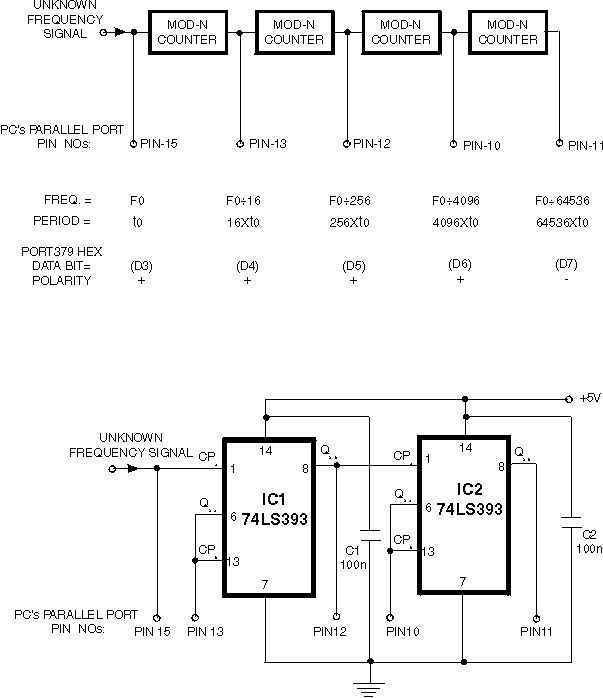
Here is a simple technique for measuring frequencies over quite a wide frequency range and with acceptable accuracy limits using a PC. It follows the basic technique of measuring low frequencies, i.e. at low frequency, period is measured for...