
Double astable multivibrator circuit diagram
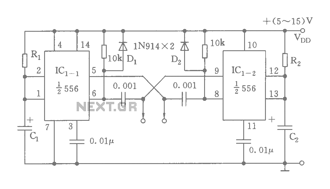
The schematic involves a 556 timer IC, which is essentially two 555 timer circuits integrated into a single package. Each half of the 556 timer can be configured as either an astable or monostable multivibrator. In the astable configuration, the circuit continuously oscillates, producing a square wave output. The frequency of oscillation is determined by the values of the resistors and capacitors connected to the timer.
In this configuration, the capacitors C1, C2, and C3 are used to set the timing intervals. By selecting equal values for these capacitors, the circuit ensures that both multivibrators operate in sync, producing clock signals that maintain a consistent phase relationship. The resistors connected to the timing capacitors also play a crucial role in defining the duty cycle and frequency of the output signals.
The output from each multivibrator can be utilized for various applications, such as clock signals for digital circuits, timing applications, or generating pulse-width modulation (PWM) signals. The ability to adjust the time constant by varying the resistor values allows for a wide range of frequencies to be generated, making this circuit versatile for different electronic applications.
Overall, the dual time base circuit utilizing the 556 timer provides a robust solution for generating synchronized clock signals with adjustable frequencies, making it suitable for use in various electronic systems where timing and synchronization are critical.As shown, the circuit consists of a dual time base circuit 556 consisting of two synchronized multivibrator, two output clock signal synchronized intervals and the oscillation frequency can be varied by adjusting the time constant, flexible and convenient . When you select C1 = C2 = C3, the oscillation frequency
Related Circuits
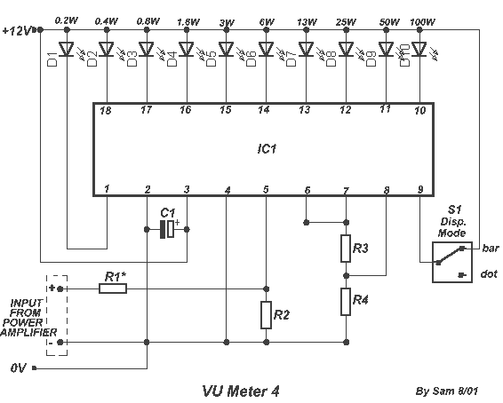
The circuit is placed parallel with the exit of power amplifier and gives the level of signal from output. Changing resistance R1 in the input circuit, we adapt the indication of power in the resistance of loudspeaker that we...
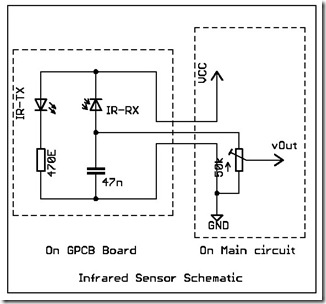
The following circuit illustrates a simple infrared sensor module circuit diagram. Features include a simple infrared sensor module and flame detection. The simple infrared sensor module circuit operates by utilizing an infrared (IR) transmitter and receiver pair. The IR transmitter...
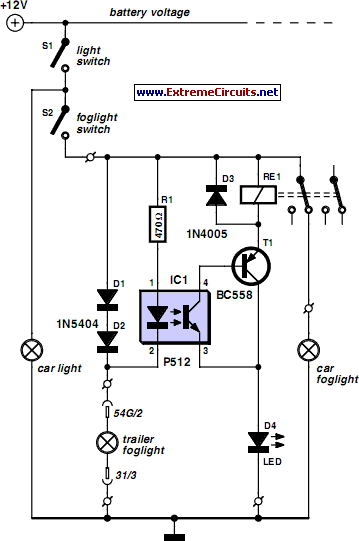
A rear fog lamp is mandatory for trailers and caravans to enhance visibility during foggy conditions. When the fog lamp is activated, the fog lamp of the towing vehicle must be turned off to prevent distracting reflections. To achieve...
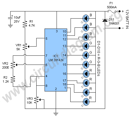
This document outlines a battery monitoring circuit designed to measure the voltage of 12V lead-acid batteries, such as those used in automobiles. The circuit utilizes the LM3914 integrated circuit (IC) along with several external components, including a series of...
The external audio spectrum display circuit is designed for high-end audio equipment, providing both real-time playback signal analysis and visually appealing effects. This display does not require any electrical connections to the sound equipment; it can simply be placed...
The circuit depicted in the figure allows for the selection of optimal operating conditions and a suitable allocation of the temperature coefficient for the resonant circuit components. The resonance occurs at both ends of the circuit. Additionally, the exchange...
Warning: include(partials/cookie-banner.php): Failed to open stream: Permission denied in /var/www/html/nextgr/view-circuit.php on line 713
Warning: include(): Failed opening 'partials/cookie-banner.php' for inclusion (include_path='.:/usr/share/php') in /var/www/html/nextgr/view-circuit.php on line 713