
frequency counter PIC-Based Digital
The frequency counter circuit is critical for accurately measuring and displaying frequency signals, particularly in radio frequency applications. The installation of the 74HC4046 phase-locked loop (PLL) is essential for frequency synthesis and demodulation, enabling the counter to process variable frequencies from the VFO. The careful adjustment of the coarse and fine pots ensures precise calibration, allowing for accurate readings that are crucial for tuning and signal analysis.
The use of diodes and NPN transistors in the automatic band switching interface provides a robust solution for integrating the frequency counter with the receiver, simplifying the user experience by automating frequency adjustments based on the selected band. The choice between a rotary switch or an interface unit offers flexibility in design, accommodating various user preferences and installation scenarios.
To mitigate noise issues, the frequency counter's mounting position and grounding scheme are paramount. The decision to allow the display to float rather than grounding it directly is a critical design consideration that addresses the interference caused by LCD circuits. This innovative approach demonstrates a practical understanding of electromagnetic interference (EMI) and grounding techniques in electronic designs.
In summary, the integration of the frequency counter into the receiver system involves careful consideration of component selection, circuit design, and mechanical installation to ensure optimal performance and minimal noise interference. The outlined procedures and precautions are essential for achieving reliable operation and accurate frequency measurements in the field.Apply power to the frequency counter and set the coarse (top pot) and fine (bottom pot) adjustments to show zero frequency on the display. Turn the pots counter-clockwise to set to zero. Sometimes the counter will show all squares and no digits. Disconnect and re-apply power and the digits should show. Also, turn the viewing angle of the display to make sure they are visible. _Install a 74HC4046 in the middle socket. This will allow VFO energy to reach the counter. (Or remove the short on the VFO cable, leave the HFO cable shorted. ) Be very careful of reverse polarity connections. A reverse polarity connection to the frequency counter will blow the voltage regulator (78LO5). Use a diode at the B+ input to the Frequency Counter if you think you might make a mistake. Band side of the diode goes to the outside where you will be attaching power. _Set the 2/8 ceramic trim pot (labeled 14. 068) to its middle position. Line up the slot in the adjustment screw with the capacitor pins, with the rotor plate on the end with the arrow. The rotor plate is the part of the top with the metallic color. If the frequency is too high, add a turn to the toroid. (This may require rewinding the toroid for a clean appearance, but having the frequency read too high, >15MHz, is unlikely.
) _Secure the VFO toroid by whatever means you have decided. Some options are a small plastic wrap, a 4-40 screw/nut and 3/16" rubber grommet (cut to fit into the center of the toroid), or pour wax from a candle (let wax cool before proceeding). Picture _Set the receiver to 40 Meters. Bandpass switch to the 40/30 side and the Crystal Filter switch to the 40/20 side. One LED should be on next to the 10. 545 relay. The offsets and the adding/subtracting are done at Pins 12 and 13 of the PIC16C71. Pins 12 and 13 are brought out to a four pin set on the back of the counter. The chip has 100K internal resistors that bias the pins to 5 volts. Two of the pins are grounds and the offsets are normally set by using a jumper to ground the necessary pins.
With this receiver, wires are soldered to the left side pins (looking at the back). The right side pins are grounds. The left side pins are labeled "upper jumper" and "lower jumper" in these instructions. There are two ways to connect the Frequency Counter to the receiver to achieve automatic switching of the bands on the counter. One is by using a small interface unit that uses diodes and two NPN transistors that connect to the switches on Board 1 of the receiver.
The second one is by using a rotary switch. The easiest one to wire is a two section rotary, either one wafer with two sections or two wafers. A rotary switch with one wafer can be used but is a little more complex to wire. Note: The "Frequency Counter" output between the VFO amplifiers will not be used to drive the Frequency Counter. This connection overdrives the Frequency Counter and causes birdies in the receiver. Getting the birdies of the counter out of the receiver has been researched for many hours. Just recently an accidental discovery showed the best way to mount the frequency counter for minimum birdies into the receiver.
Almost all the noise from the counter comes from the LCD updating circuit and is radiated by the display bezel and the display itself. Normally one would think that using good grounding techniques would eliminate that noise. However, when adjusting the counter frequencies one day, the display was insulated from ground and there was no display noise in the receiver!
A ground loop with the display must make the noise float in the ground circuit of the receiver. Therefore, when mounting the frequency counter, DO NOT ground the display, let it float! The only ground to the display should be at the back of the PIC PCB ground connection on the back of the counter. Turns out #12 solid copper wire scrapped from house wiring fits very nicely inside the mounting holes of the display.
🔗 External reference
Related Circuits

This design circuit serves as a converter utilizing the LM2623A ratio adaptive circuit to drive a digital camera motor. It generates 5 volts from input voltages that range between 1.8 and 4.5 volts. The circuit's duty cycle, while not...
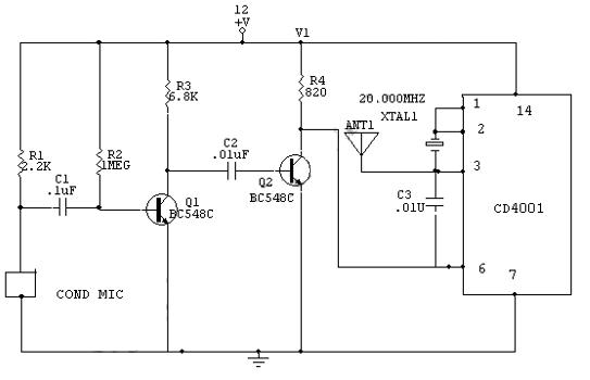
This is a transmitter circuit that can transmit both FM and AM signals simultaneously at two different frequencies: FM at 100 MHz and AM at 20 MHz. The described transmitter circuit is designed to operate at two distinct frequency...
An audio frequency signal generator can output audio signals, 465 kHz spectral amplitude signals, and 52.5 Hz to 16 kHz high-frequency amplitude-modulated signals. The high-frequency oscillator's vibration frequency is determined by the components G and L. A variety of...
There is an interest in creating an interactive LED game board or a "Stargate" DHD-type sci-fi prop, where each tile is illuminated from below by either a single white LED or an RGB combination. The goal is to make...
The SI2171 is a sub-package of the SI2170. For further details, please refer to the SI2170 description. The datasheet for the SI2171 can be downloaded from the link provided below. By Silicon Laboratories. The SI2171 is a versatile integrated circuit...
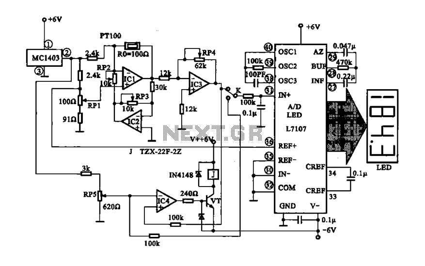
The digital display temperature detection circuit utilizes a precision digital display to indicate temperature readings. The circuit employs the MC1403, which outputs a reference voltage, with the potentiometer RP5 setting the reference value for the inverting terminal (a) of...