
Frequency Divider
Part List
R1= 10Kohm R8= 47 ohm IC1= 4011
R2= 100Kohm R9-10-11= 100Kohm T1= 110/220Vac //8V 100mA
R3= 680 ohm C1= 1000uF 25V D1-2= 1N4007
R4= 1Mohm C2-3= 100nF 100V ceramic D3= 5.1V 0.5W Zener
R5-6-7= 100Kohm C4-5= 100pF ceramic D4-5= 1N4148
This circuit functions as a frequency divider using a T-type flip-flop configuration, specifically implemented with the 4011 integrated circuit, which contains four NAND gates. The primary operation involves taking an input sine wave, rectifying it to a square wave, and then using the T-flip-flop to divide the frequency by two.
The input signal, typically a 50 Hz sine wave, is first conditioned to limit the negative half of the waveform. This is accomplished through appropriate resistor and capacitor values that ensure the waveform transitions to a square wave. The square wave is then fed into the T-flip-flop, which toggles its output state with each clock pulse received, effectively halving the frequency. Thus, from an input of 50 Hz, the output pulse frequency is 25 Hz.
Power for the circuit is supplied at +5V, which is sufficient for the low current requirements of the flip-flop circuit. The components listed, including resistors, capacitors, and diodes, are selected to ensure proper voltage levels and signal integrity throughout the operation. The use of a Zener diode provides voltage regulation to protect the circuit from over-voltage conditions, while the 1N4007 diodes are used for rectification purposes.
Overall, this frequency divider circuit is a reliable and efficient solution for applications requiring frequency halving, with minimal power consumption and component count. This is a classic divider of frequency via two. It is achieved with a classic circuit T-flipFlop, round IC1 [ 4011 ]. In the circuit, the frequency of network, after are limit the negative half-s period of sine wave and transform in square wave, are divided via two. Thus for frequency50 HZ, we will take in the exit pulse of frequency 25 HZ. The supply of circuit it is + 5V and does not need high benefit in current. Part List R1= 10Kohm R8= 47 ohm IC1= 4011 R2= 100Kohm R9-10-11= 100Kohm T1= 110/220Vac //8V 100mA R3= 680 ohm C1= 1000uF 25V D1-2= 1N4007 R4= 1Mohm C2-3= 100nF 100V ceramic D3= 5.1V 0.5W Zener R5-6-7= 100Kohm C4-5= 100pF ceramic D4-5= 1N4148 🔗 External reference
Related Circuits
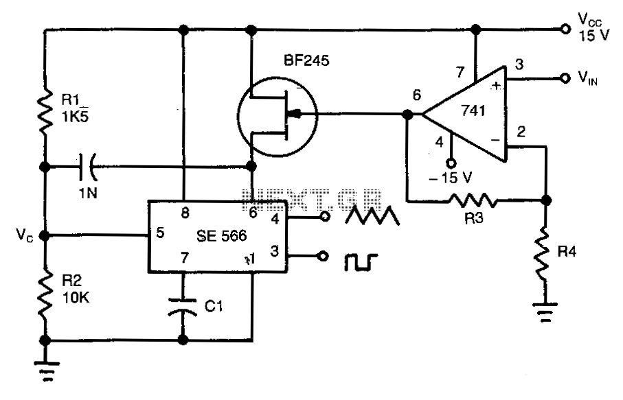
This circuit operates based on the frequency variation of the function generator in relation to the input voltage (ViN). The frequency is influenced by the capacitance and resistor connected to pin 6, with the resistor being substituted by a...
Power input is to a 7805 5 volt regulator. A pair of LEDs is connected between the 5 volt supply and ground, with current limiting resistors in series and one pin on the AT90S2313 shunts the current through one...
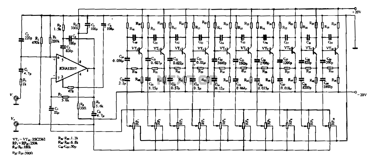
Figure 1-97 illustrates a ten-band equalizer circuit with its initial connection. Figure 1C represents the utility voltage amplifier, with R7 functioning similarly to the island depicted in Figure 1-92 R1. Additionally, R2 and the transistors VTr to VTio form...
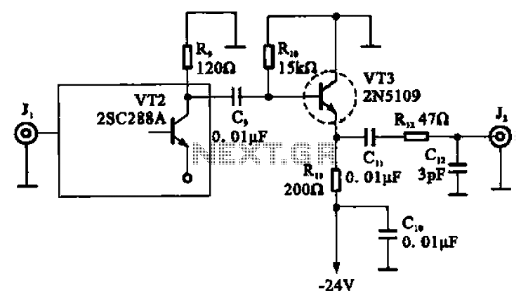
A high-frequency signal is displayed in the output amplifier. The circuit consists of a VI3 common collector amplifier (emitter follower) designed to enhance the child-band. It is a high-frequency amplifier (1-250 MHz) that increases the output voltage and boosts...
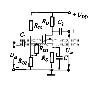
FET several basic bias circuit - self-bias voltage divider circuit The self-bias voltage divider circuit is a fundamental configuration used in Field Effect Transistor (FET) biasing. This circuit employs two resistors to create a stable bias voltage for the transistor's...
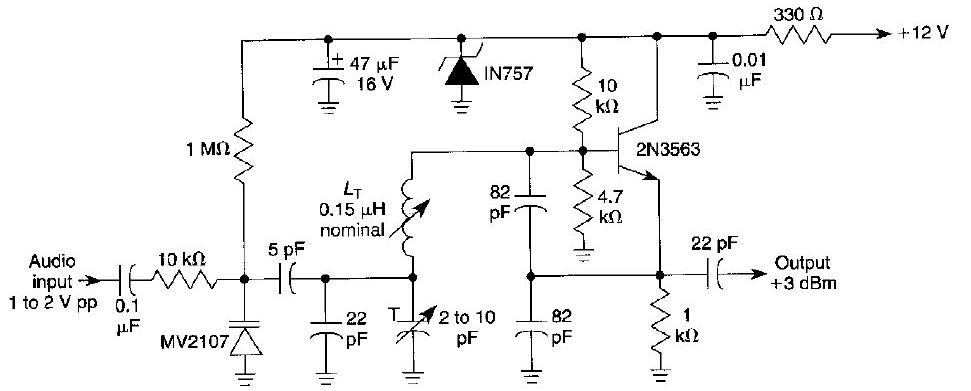
This FM oscillator can be utilized for wireless audio, microphone, and part-15 applications where a stable frequency-modulated oscillator is required. The FM oscillator is an essential component in various communication systems, particularly in wireless audio transmission and microphone applications. It...