
Frequency Meter and Pulse Generator with AT902313
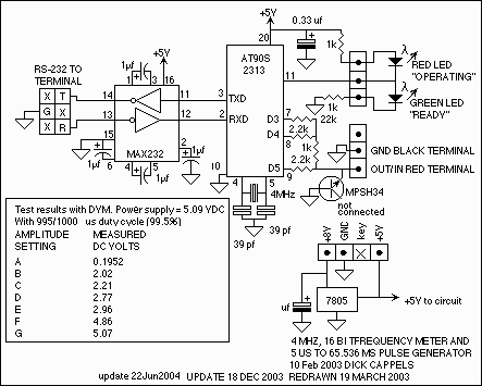
The circuit design begins with a 7805 voltage regulator, which provides a stable 5V output from a higher voltage input. This regulated voltage serves as the primary power supply for the entire circuit. Two light-emitting diodes (LEDs) are connected in parallel between the 5V supply and ground, each accompanied by a current-limiting resistor to prevent excessive current flow. The AT90S2313 microcontroller controls which LED is illuminated by shunting current through one LED at a time, indicating the operational state of the device. One LED signifies that the system is in a standby state, while the other indicates active operation, providing immediate visual feedback to the user.
The microcontroller also incorporates a built-in Universal Asynchronous Receiver-Transmitter (UART) for serial communication. This UART interfaces with the external environment through an RS-232 connection, facilitated by the Maxim MAX232 chip, which converts the 5V logic levels to RS-232 compatible voltage levels, enabling communication with other devices.
The pulse generator output is configured using a resistor ladder network, which allows for the generation of various pulse amplitudes suitable for driving 5V CMOS devices. Pin 9 of the AT90S2313 functions as both an input and output, serving as the most significant bit (MSB) in the ladder network. This configuration ensures that it can handle the full amplitude input signal without any attenuation.
To enhance the robustness of the circuit against electrostatic discharge (ESD) and accidental handling of test leads, a bipolar transistor is incorporated. The emitter-base junction of the transistor is reverse-biased under normal conditions, but it will avalanche when subjected to high positive voltages, providing a protective measure. When the voltage swings negative, the junction enters forward conduction, safeguarding the sensitive components downstream.
The frequency measurement aspect of the circuit is achieved using a frequency reference generated by a 74HCT4060 divider circuit and a 4 MHz crystal oscillator, which is further divided by a 74HCT4040 to achieve the desired frequency outputs. The accuracy of the frequency meter is validated against a known reference, ensuring that it remains within a two-count deviation from the measured output.
While a printed circuit board (PCB) is not strictly necessary for assembly, careful layout considerations are recommended. It is advisable to position the crystal and its load capacitors close to the associated pins on the AT90S2313 to minimize parasitic capacitance. Additionally, keeping the I/O circuitry separate from the crystal circuitry aids in reducing potential interference, which is facilitated by the physical layout of the components.Power input is to a 7805 5 volt regulator. A pair of LEDs is connected between the 5 volt supply and ground, with current limiting resistors in series and one pin on the AT90S2313 shunts the current through one LED or the other. When one LED is on, the device is "ready", that is not generating pulses on the output and not measuring input frequency.
When the other LED is on, the devise is actively generating pulses or measuring frequency. As a consequence, one of the LEDs is on at a time allowing quick visual confirmation that power is applied and the state of the device. The serial interface is the AT90S2313's internal UART connected to the outside world via RS-232 using a Maxim MAX232 interface chip, which derives RS-232 drive voltages from the 5 volt supply.
The output of the pulse generator is via a resistor ladder network. I chose the values I did so that I would have a few low-amplitudes to select from and still be able to drive 5 volt CMOS with the maximum level pulses. If I were to do it over, I would probably just use an R-2R ladder network. Pin 9 doubles as an input and output pin, thus it is connected as the MSB of the ladder network so that it can be exposed to the full amplitude input signal (without attenuation).
To provide a measure of protection against electrostatic discharge and clumsy handling of test leads, a reverse biased emitter-base junction of a bipolar transistor is used. The junction will avalanche when the voltage exceeds at high positive voltages and enters forward conduction when the voltage swings negative.
The collector of the transistor is left floating. I trimmed the frequency meter timing loops by measuring the output of a frequency reference I made with a 74HCT4060 and a 4 MHz crystal and a 74HCT4040 12 stage divider. The fifth harmonic of the '4060 was zero beat with NIST station WWV by padding the capacitance from the crystal terminals to ground.
The frequency meter was consistently within two counts of the output of frequency reference that was being measured. You can build this without needing a printed circuit board, though it you really are anxious to, it sure would look neat.
Layout isn't really critical, except that its a good idea to put the crystal and its load capacitors next to their associated pins on the AT90S2313, and its also a good idea to keep the I/O circuitry clear of the crystal circuitry. This should fall our naturally since, with the expectation of pin 9, the output pins are on the opposite side of the chip from the oscillator.
The serial interface is the AT90S2313's internal UART connected to the outside world via RS-232 using a Maxim MAX232 interface chip, which derives RS-232 drive voltages from the 5 volt supply. The output of the pulse generator is via a resistor ladder network. I chose the values I did so that I would have a few low-amplitudes to select from and still be able to drive 5 volt CMOS with the maximum level pulses.
If I were to do it over, I would probably just use an R-2R ladder network. Pin 9 doubles as an input and output pin, thus it is connected as the MSB of the ladder network so that it can be exposed to the full amplitude input signal (without attenuation). To provide a measure of protection against electrostatic discharge and clumsy handling of test leads, a reverse biased emitter-base junction of a bipolar transistor is used.
The junction will avalanche when the voltage exceeds at high positive voltages and enters forward conduction when the voltage swings negative. The collector of the transistor is left floating. 🔗 External reference
Related Circuits
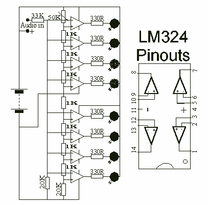
This circuit uses two quad op-amps to form an eight LED audio level meter. The op-amp used in this particular circuit is the LM324. It is a popular IC and should be available from many parts stores. More: The...
The circuit described is a simple sound level meter, also known as a VU meter, which helps monitor sound levels to prevent hearing loss caused by loud music. It is a passive type of meter, requiring no separate power...
A DIY intervalometer for the Sony NEX 5N camera designed for time-lapse photography. This intervalometer is compatible with most Sony cameras, including the NEX and Alpha series. The circuit utilizes an infrared LED and a Serial LCD with four...

This is a circuit for an audio frequency meter. This circuit utilizes a 555 IC configured as a monostable multivibrator (one-shot trigger). A monostable multivibrator can function as a frequency-to-voltage converter by producing a fixed pulse width, with the...
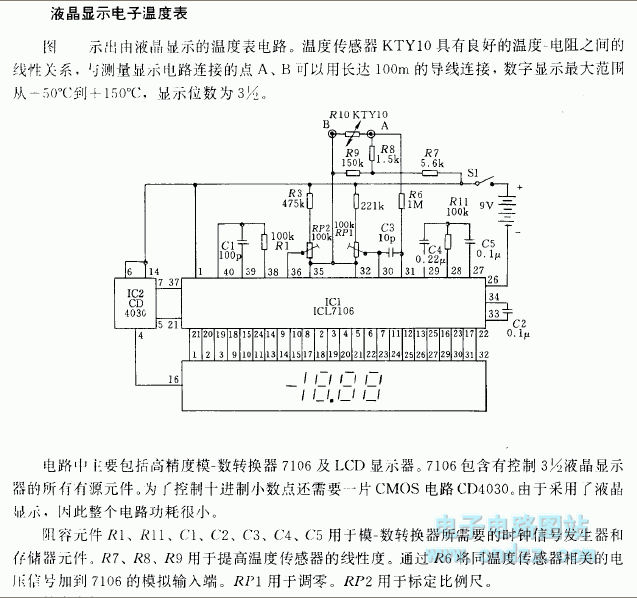
Related components PDF download: ICL7106CD4036. The LCD electronic thermometer circuit is illustrated. The temperature sensor KTY10 exhibits a strong linear relationship between temperature and resistance. Points A and B (Measurement display circuit) can be connected with a 100-meter wire....
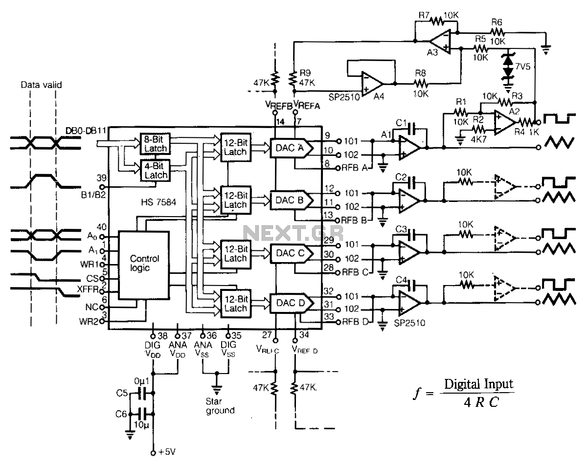
The programmable multiple output generator provides control signals for the data converter automated test equipment (ATE). Major performance criteria include simple interfaces with various microprocessor systems, low power consumption, stable output timing relationships, and minimal board space requirements. For...
Warning: include(partials/cookie-banner.php): Failed to open stream: Permission denied in /var/www/html/nextgr/view-circuit.php on line 713
Warning: include(): Failed opening 'partials/cookie-banner.php' for inclusion (include_path='.:/usr/share/php') in /var/www/html/nextgr/view-circuit.php on line 713