
Ten-segment frequency equalizer
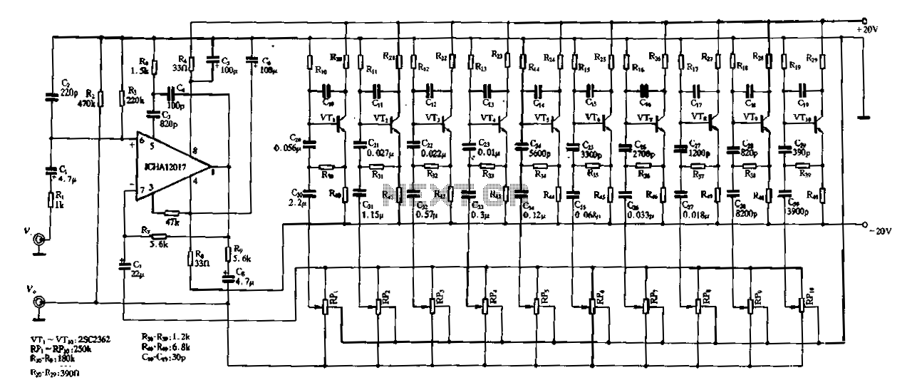
The ten-band equalizer circuit is designed to allow precise control over audio frequency ranges, providing the capability to enhance or attenuate specific bands of audio signals. The circuit utilizes a voltage amplifier, which is critical for maintaining signal integrity and ensuring that the output levels are consistent across all bands. The resistive components, such as R7 and R2, are integral in setting the gain and shaping the frequency response of the equalizer.
The configuration of ten transistors, labeled from VTr to VTio, is employed to create an inductor simulation, which allows for the emulation of inductive behavior without the need for physical inductors. This approach can significantly reduce the size and weight of the circuit while maintaining performance. Each transistor can be controlled to vary the impedance at different frequency bands, thus contributing to the overall equalization process.
The bandpass filter resonance capacitance, represented by C39, is crucial for defining the bandwidth of each frequency band. This component works in conjunction with resistors and the transistor network to create a filter that allows only a specific range of frequencies to pass through while attenuating others. The reference to equivalent capacitances (C1, C20 to C29) in Figure 1-93(b) indicates that these capacitors are selected to match the desired frequency response characteristics of the equalizer, ensuring that the circuit performs optimally across the audio spectrum.
In summary, the ten-band equalizer circuit utilizes a combination of voltage amplification, resistive elements, and transistor-based inductor simulation to achieve a versatile and efficient audio processing solution. The careful selection and arrangement of components are essential for achieving the desired frequency response and maintaining signal fidelity.Figure 1-97 is a ten-band equalizer circuit with a first connection thereof. FIG lC is the utility voltage amplifier, R7, respectively, equivalent to the island in Fig 1-92 Rl, R2, VTr-VTio ten transistors is mainly composed of inductor simulation, ~ C39 is the band bandpass filter resonance capacitance, corresponding to FIG. 1-93 (b) in C1, C20 ~ lC29 equivalent C2 0
Related Circuits
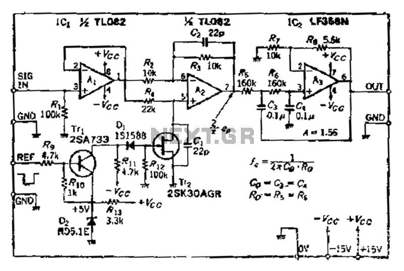
After turning off TT2, the input signal enters through chi Az, where the input resistance is very high and reaches the same potential. The inverting input terminal must also be associated with this movement. Therefore, Trr functions as a...
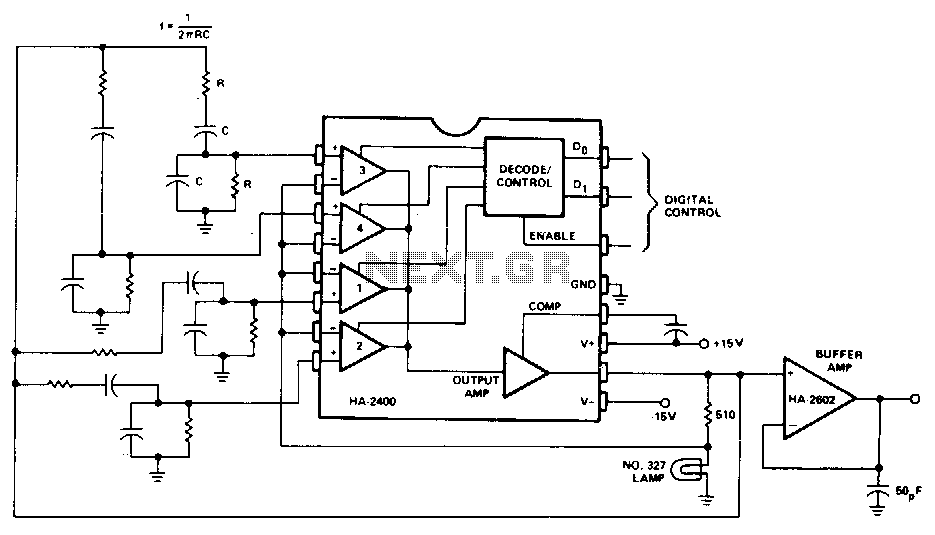
A Wien-bridge oscillator can be made variable by utilizing two frequency-determining components that are adjusted simultaneously with high tracking accuracy. However, high-quality tracking potentiometers or variable capacitors are often costly and challenging to procure. To circumvent the need for...
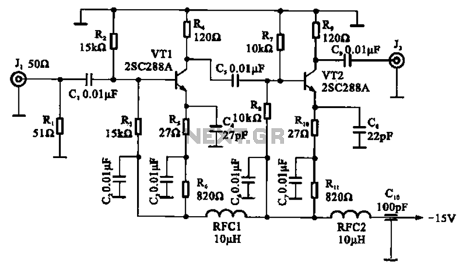
A wideband high-frequency amplifier circuit is presented, utilizing resistance and capacitance coupling in a common emitter configuration to amplify high-frequency signals. When a high-frequency signal with an input impedance of 50 ohms is applied to the amplifier through a...
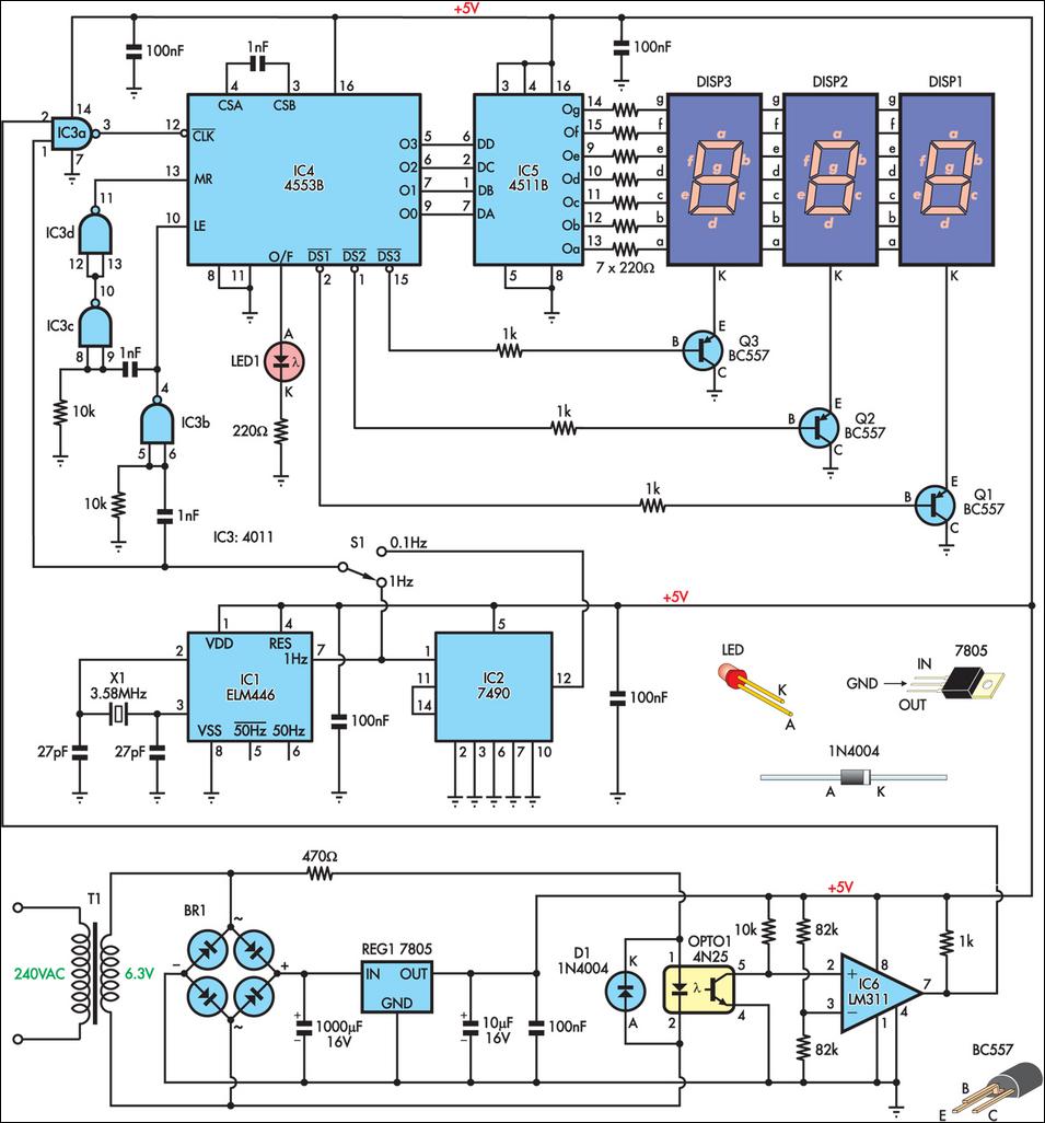
This is a simple frequency counter designed to monitor the 240VAC mains supply. It has a frequency range of 0-999Hz, making it suitable for use with 400Hz equipment as well. Standard TTL/CMOS logic is employed for the counters and...

A project is underway that necessitates the conversion of a 0-10V DC supply into a linear frequency range in the form of a square wave. The project involves designing a circuit that takes a direct current (DC) voltage input ranging...
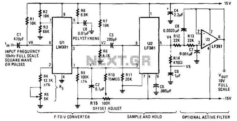
U1 is a frequency-to-voltage converter that feeds a sample-and-hold circuit utilizing an LF381 operational amplifier. An LF351 provides a 10-V maximum scale output. The circuit generates a 1-V output per kHz frequency. The described circuit employs a frequency-to-voltage conversion technique,...