
Frequency doubler
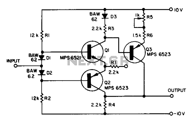
The proposed circuit modification involves integrating additional components into a standard complementary symmetry class AB buffer configuration, which is commonly used for audio amplification and signal buffering. The primary objective of this modification is to achieve frequency doubling of an input sine wave signal.
In this configuration, Q3 serves as an additional transistor that enhances the buffer's ability to handle higher frequencies. The inclusion of D3, a diode, plays a critical role in shaping the waveform and ensuring that the output maintains the integrity of the signal during the frequency doubling process. The resistors R3 through R6 are strategically placed to control the biasing and gain of the transistors, ensuring optimal performance at the designated frequency of 1 MHz.
The operation of this circuit can be understood through the principles of nonlinear mixing, where the input sine wave is subjected to a non-linear transfer characteristic introduced by the diode and the transistors. This interaction results in the generation of harmonics, with the second harmonic being the primary focus for frequency doubling.
The careful selection of resistor values is crucial to achieving the desired performance. R3 and R4 typically set the biasing conditions for Q3, while R5 and R6 may be used to stabilize the output and control the gain. The circuit's design must ensure that the transistors operate within their active regions to maintain linearity and prevent distortion.
In summary, the integration of Q3, D3, and resistors R3 through R6 into a conventional complementary symmetry class AB buffer enables the circuit to effectively double the frequency of an input sine wave, achieving operational effectiveness at 1 MHz. This configuration is beneficial in applications requiring frequency manipulation while maintaining signal fidelity.Adding components Q3, D3, and resistors R3 through R6 to a conventional complementary symmetry class AB buffer can double the frequency of an input sine wave. The circuit works at 1 MHz. 🔗 External reference
Related Circuits
The AD654 is a monolithic voltage-to-frequency (V/F) converter that comprises an input amplifier, a precision oscillator system, and a high-current output stage. A single resistor-capacitor (RC) network is all that is needed to configure any full-scale (FS) frequency up...
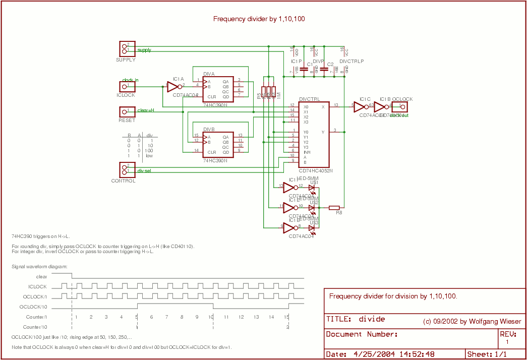
The divider design is straightforward. Users can select a division factor of 1, 10, or 100, or opt for no output (tied low) through the CONTROL input connected to the analog multiplexer HC4052. The design utilizes AC04 to drive...

This circuit is designed for an RF (radio frequency) transmitter experiment, where a watt meter is instrumental in optimizing the transmitter circuit. A simple RF watt meter circuit is illustrated in the schematic diagram below. The circuit is not...
The LM2889 is designed to interface audio and video signals to the antenna terminals of a television receiver. It consists of a sound subcarrier oscillator, an FM modulator, a video clamp, and RF oscillators and modulators for two low-VHF...
My generator can produce sine- and squarewaves with frequencies between 1 Hz and 100 kHz and amplitudes ranging from zero to 1.55 Veff in 600 Ohms. Sinewave distortion is 0.1% or less between 20 Hz and 20 kHz, somewhat...

This inexpensive frequency meter circuit is suitable for general use in small laboratories. It is cost-effective, easy to construct, and sufficiently reliable for most electronics enthusiasts. The frequency can be directly read from the meter, with a measurement range...