
Frequency limit detector
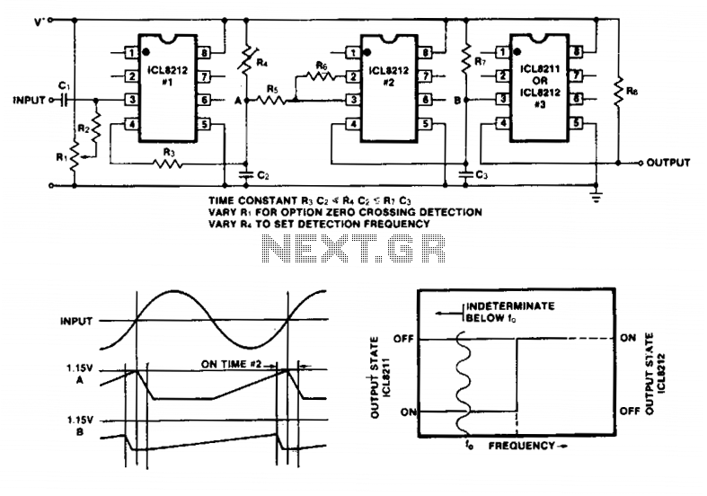
The described circuit utilizes the ICL8211 and ICL8212 integrated circuits to create a frequency limit detector that outputs a GO/NO-GO signal based on varying amplitude input signals. The first ICL8212 functions as a zero-crossing detector, which is critical for accurately detecting the transition points of the input waveform. The output stage, consisting of resistors R3, R4, and capacitor C2, generates a slow ramp signal in the positive direction. This ramp is characterized by a slower response compared to the negative transition, which is achieved through the careful selection of component values.
Resistors R5 and Rg introduce hysteresis into the circuit, ensuring that the second ICL8212 remains activated long enough to discharge capacitor C3 effectively. This design consideration is essential for maintaining stability in the output signal, particularly in the presence of noise or fluctuations in the input signal. The time constant defined by the combination of R7 and C3 is significantly larger than that of R4 and C2, which serves to further refine the response characteristics of the circuit.
For applications requiring specific output polarities corresponding to low and high input frequencies, either the ICL8211 or ICL8212 can be selected as the output driver based on the desired operational parameters. It is important to note that the circuit's performance is contingent upon a stable power supply, as variations in supply voltage can adversely affect the sensitivity and accuracy of the detector. Additionally, at very low frequencies, the output will closely follow the input frequency, which may be beneficial for certain applications requiring real-time frequency tracking.Simple frequency limit detectors providing a GO/NO-GO output for use with varying amplitude input signals may be conveniently implemented with the ICL8211/8212. In the application shown, the first ICL8212 is used as a zero-crossing detector. The output circuit consisting of R3, R4 and C2 results in a slow output positive ramp. The negative range is much faster than the positive range. R5 and Rg provide hysteresis so that under all circumstances the second ICL8212 is turned on for sufficient time to discharge C3.
The time constant of R7C3 is much greater than R4C2. Depending upon the desired output polarities for low and high input frequencies, either an ICL8211 or an ICL8212 may be used as the output driver. The circuit is sensitive to supply voltage variations and should be used with a stabilized power supply. At very low frequencies the output will switch at the input frequency. 🔗 External reference
Related Circuits
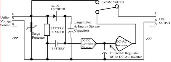
Thomas Edison developed the incandescent light bulb, which operated from a 110-volt DC source. The primary drawback of DC power was that it could only be distributed over short distances without needing to be regenerated. In the early 1900s,...
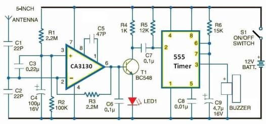
Cellular phone detector circuit schematic using common electronic parts The cellular phone detector circuit is designed to identify the presence of a cellular phone within a specified range. This circuit utilizes basic electronic components, making it accessible for hobbyists and...
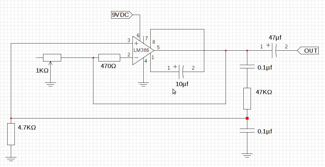
The design utilizes the LM386n-1 integrated circuit, powered by a single power supply to maintain a compact layout. There is a need to control the frequency, and the user is inquiring about which component values should be adjusted for...
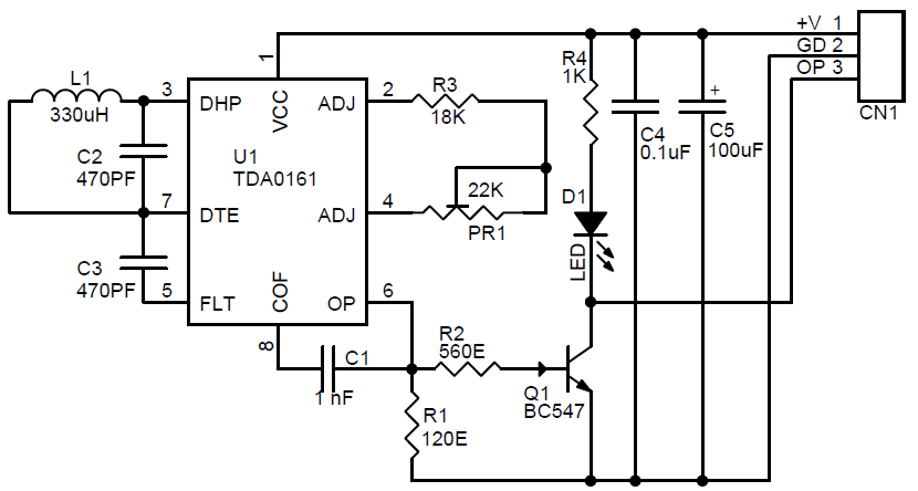
The metal detector project is designed for detecting metallic objects by sensing variations in high-frequency eddy current losses. It employs an externally-tuned circuit that functions as oscillators. The output signal level is modified by the presence of an approaching...

This design circuit is a tachometer circuit based on the LM2907 integrated circuit, which can provide zero-crossing data to a digital system. At each zero crossing of the input signal, the charge pump alters the state of capacitor C1...
Here is a straightforward lie detector that can be assembled in a matter of minutes and can be very useful for determining if someone is telling the truth. While it is not as advanced as professional models, it is...