
LED Thermometer
The LED thermometer circuit employs the LM34DZ temperature sensor, which provides a linear voltage output proportional to temperature. The design is suitable for home applications, specifically for monitoring indoor temperatures. The choice of LED colors allows for aesthetic customization, but it is important to consider the forward voltage drop associated with different LED types. The circuit's operation mode, either dot or graph, is determined by the configuration of pin 9 on U2, which influences the visual representation of the temperature readings.
Calibration is a critical step in ensuring accurate temperature measurements. The procedure involves adjusting resistors R5 and R7 to specific voltage levels that correspond to the expected outputs of the LM34DZ sensor at known temperatures. The final adjustment of R1 ensures that the circuit maintains proper scaling, allowing for accurate readings across the intended temperature range.
The design can be further modified to extend the operating range of the LM34DZ by altering the voltage reference. However, this modification may compromise precision, necessitating careful consideration based on the application's requirements. The use of standard electronic components, such as resistors and voltage references, makes this circuit easily replicable and adaptable for various home temperature monitoring needs.This LED thermometer is designed for in home use, to read temperatures between about 60 and 78 degrees Fahrenheit. It is based around a precision temperature sensor IC, the LM34DZ. This sensor require no calibration and can measure temperatures of between -50F and 300F. While the circuit shown here does not use the full range of that sensor, it ca n be modified to do so by simply changing the voltage reference to U2 at the sacrifice of precision. You can use any LED you want for D1 - D10, however blue LEDs have a higher voltage requirement so if you want to go blue for a modern look, they may appear more dim then red, yellow or green. By leaving pin 9 of U2 disconnected, the graph will operate in dot mode and R8 should be 100 Ohm. If you build the circuit with pin 9 tied to 9V, the circuit will be in graph mode and R8 should be 15 Ohms.
To calibrate the circuit, you will need a voltmeter. Power the circuit up and let it sit for a few minutes for temperature to stabilize. Ground the negative lead of the meter and connect the positive lead to pins 6 and 7 of U2. Set R7 so the meter reads as close to 3. 345V as possible. Now connect the positive lead of the meter to pin 4 of U2 and adjust R5 until the meter reads 2. 545V. Finally, disconnect power to the circuit and remove U1 and U2 from their sockets. Measure the value of R3 with an ohmmeter and remember that value. Connect the ohmmeter across R1 and adjust R1 to a value of exactly 3 times the value of R3. Reinstall U1 and U2 and the circuit is ready for use. 🔗 External reference
Related Circuits
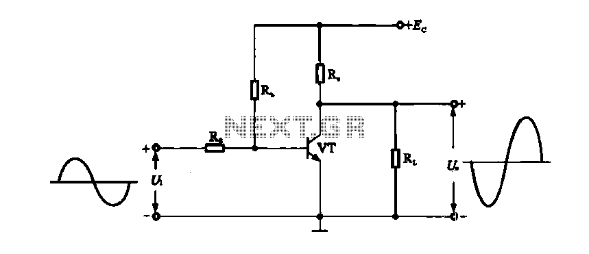
A DC-coupled single-tube amplifier is a circuit that utilizes a single transistor to amplify DC signals. This configuration primarily consists of a transistor, bias resistors, and minimal coupling capacitors. The absence of coupling capacitors allows the DC operating states...
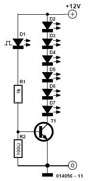
This simple and inexpensive circuit is not limited to Christmas. It consists of two resistors, a small-signal transistor such as a BC547, one flashing LED, and a string of standard LEDs. The flashing LED functions as an oscillator, turning...
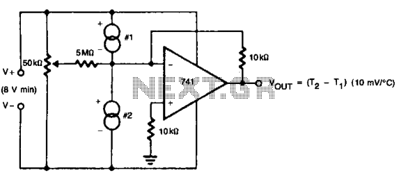
The 50 k ohm potentiometer adjusts offsets in devices, whether internal or external, allowing for the setting of the difference interval size. This feature makes it suitable for liquid-level detection, particularly in scenarios where a measurable temperature difference exists. The...

A dimming control circuit generates a dimming control signal to determine the brightness of at least one light-emitting diode. The dimming control signal consists of multiple bright-dark cycles, each comprising a bright phase and a dark phase. The bright...
Circuit of a crystal-controlled FM transmitter. The circuit utilizes a crystal oscillator and several power amplifier stages to enhance output power. The crystal-controlled FM transmitter circuit is designed to generate frequency-modulated signals with high stability and precision. At the core...
The 555 circuit below is a flashing bicycle light powered with three C or D cells (4.5 volts). The two flashlight lamps will alternately flash at an approximate 1.5 second cycle rate. Using a 4.7K resistor for R1 and...
Warning: include(partials/cookie-banner.php): Failed to open stream: Permission denied in /var/www/html/nextgr/view-circuit.php on line 713
Warning: include(): Failed opening 'partials/cookie-banner.php' for inclusion (include_path='.:/usr/share/php') in /var/www/html/nextgr/view-circuit.php on line 713