
Frequency Peak Detecting Probe
So...what's special about this peak detector? This peak detector's quick response time while maintaining a low droop rate, which is necessary to maintain accuracy at low frequencies is owed to the presence of the dual time constant peak detector. The 100 µF capacitors and 100 K resistor provide a 500 ms time constant peak detector. This 500 ms peak detector is coupled through a diode to the 22 µF capacitor pair. Normally, the 100 µF capacitor pair is kept charged at one diode drop above the signal's peak voltage, which is the same voltage as the 22 µF capacitors are charged to. The time constant on the 22 µF capacitor is very long, primarily determined by the capacitors and the input leakage on the op amp. This long time constant is what makes the high accuracy possible at low frequencies. The voltage on the 100 µF capacitors droops between pulses, but not until the frequency drops below 5 Hz does the ripple get to be large enough to "reach through" the series diode between the 100 µF pair and the 22 µF pair, and affect the voltage on the 22 µF pair.
The circuit employs an LM324 quad operational amplifier, which is a versatile component commonly used in analog signal processing. The first op-amp functions as a power supply splitter, deriving dual supply voltages from a single 9V battery. This arrangement is essential for creating a virtual ground reference point, enhancing the circuit's capability to handle bipolar signals. The voltage divider at the upper-left of the circuit enables the system to accept input voltages up to 15V without damaging sensitive components.
The inclusion of a 10kΩ resistor in series with the switch after the voltage divider is a critical safety feature. It limits the current entering the op-amp in the event of an overvoltage situation, protecting the circuit from potential damage. Following this resistor are two diodes that clamp the input voltage to safe levels, ensuring that the op-amp operates within its specified range.
The operational amplifier configured as a unity gain buffer ensures that the input signal is accurately represented at the output without amplification, although it could be modified to serve as a gain stage if increased sensitivity is required. The subsequent op-amp is responsible for driving two peak detectors, with a double-pole double-throw (DPDT) switch allowing for selection between the positive and negative peak detection modes. This feature enables flexibility in measuring varying signal characteristics.
The dual time constant peak detector design is noteworthy for its ability to respond quickly while minimizing voltage droop, which is crucial for accurate low-frequency measurements. The combination of a 100 µF capacitor and a 100 kΩ resistor establishes a time constant of 500 ms, allowing the peak detector to capture signal peaks effectively. The coupling of this stage to a secondary 22 µF capacitor pair through a diode serves to maintain the peak voltage level, with the long time constant of the 22 µF capacitors ensuring stability and accuracy at lower frequencies.
Overall, this circuit is a sophisticated solution for peak detection, offering high precision and versatility for a variety of applications in electronic measurement and analysis.This is a handy companion for a digital voltmeter. Its allowed me to do a lot of things I used to use my oscilloscope for, and in addition it measures voltages to much greater precision.Using an LM324 quad op amp, this peak detector provides 2% measurement accuracy on square waves from 5 Hz to 20 kHz. Taking the circuit from left-to-right, the first op amp (lower-left corner, inputs pins 8 and 9) is a power supply splitter.
It splits the 9 volt battery to make plus and minus 4.5 volts, providing a virtual ground at its output. At the upper-left a voltage divider allows the circuit to operate with up to a 15 volt full-scale input.
The 10k resistor in series with the switch following the voltage divider limits current in case the input voltage exceeds the power supply current. The two diodes after the 10k resistor limit the input voltage at the input (pin 12) of the op amp. This op amp is a unity gain buffer and serves no immediate use, though it could be connected as a gain stage to increase the peak detector's sensitivity, at the cost of bandwidth.
The next op amp (pins 1,2, and 3) drives two diode peak detectors. The dpdt switch selects which of the two peak detectors is buffered by the last op amp, thus closing the loop around the output voltage for either the positive peak or the negative peak. (Note that in the schematic there appear to be two SPDT switches, but they are really ganged as DPDT.) The other section of the dpdt switch connects a diode from the output of the op amp to the input to prevent the op amp from going open loop -doing so would cause an accuracy problem at high frequencies because the op amp takes some time to come out of saturation and close the loop.
The tricky part of the circuit is the two-stage peak detector. So...what's special about this peak detector? This peak detector's quick response time while maintaining a low droop rate, which is necessary to maintain accuracy at low frequencies is owed to the presence of the dual time constant peak detector. The 100 uf capacitors and 100 K resistor provide a 500 ms time constant peak detector. This 500 ms peak detector is coupled through a diode to the 22 uf capacitor pair. Normally, the 100 uf capcitor pair is kept charged at one diode drop above the signal's peak voltage, which is the same voltage as the 22 uf capacitors are chaged to.
The time constant on the 22 uf capcitor is very long, primarily determined by the capacitors and the input leakage on the op amp. This long time constant is what makes the high accuracy possible at low frequencies. The voltage on the 100 uf capacitors droops beween pulses, but not until the frequency drops below 5 Hz does the ripple get to be large enough to "reach through" the series diode between the 100 uf pair and the 22 uf pair, and affect the voltage on the 22 uf pair.
🔗 External reference
Related Circuits
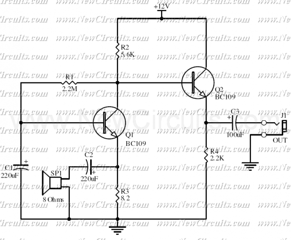
This circuit allows you to use a cheap loudspeaker as a microphone. Sound waves reaching the speaker cone cause fluctuations in the voice coil. The voice coil moving in the speaker's magnetic field will produce a small electrical signal. The...
The following circuit enables measurement of the inductance of the inductor labeled LX, which is the inductance to be measured. The output of the circuit is a TTL square wave whose frequency relates to the inductance being measured. The...
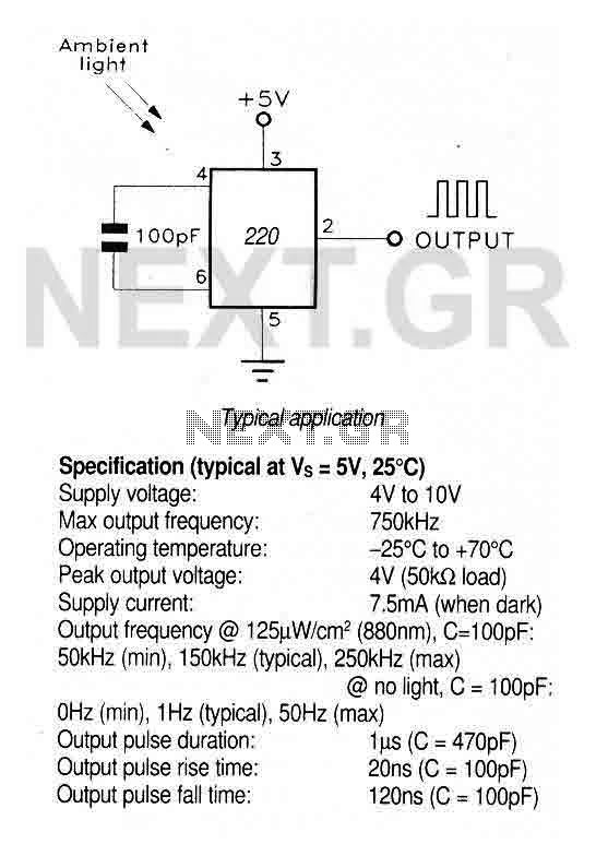
A large area photodiode and current-to-frequency converter integrated into a clear plastic 8-pin DIL package. The output generates a pulse train whose frequency is directly proportional to the light intensity. It is CMOS compatible (a 3.3kΩ pulldown resistor is...
This circuit diagram illustrates the conversion of a speaker into a microphone. When sound waves impact the diaphragm of a speaker, fluctuations occur in the coil, generating an induced voltage. This induced voltage is typically substantial but low in...
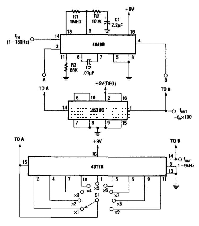
For multiplying frequencies in the 1 to 150 Hz range, this circuit utilizes a 4046B phase-locked loop (PLL) and a 100 prescaler. The output from the voltage-controlled oscillator (VCO) is phase-locked to the low-frequency input. This configuration facilitates the...
One of the simplest methods of metal detection is through a beat frequency oscillator. The circuit consists of two balanced oscillators: one provides a reference signal, while the other acts as the detector element. The frequency of the reference...
Warning: include(partials/cookie-banner.php): Failed to open stream: Permission denied in /var/www/html/nextgr/view-circuit.php on line 713
Warning: include(): Failed opening 'partials/cookie-banner.php' for inclusion (include_path='.:/usr/share/php') in /var/www/html/nextgr/view-circuit.php on line 713