
A DC motor PWM speed control circuit
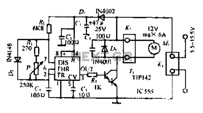
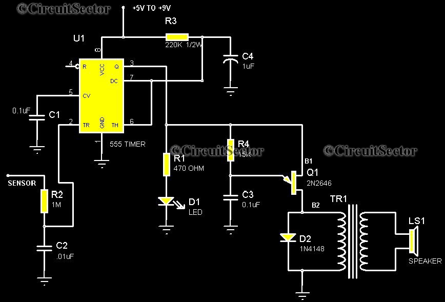
Most governors in electronic circuits employ pulse width modulation (PWM) and pulse position modulation (PPM) techniques for efficient control of motor operations. The 555 timer IC is a prevalent choice for generating precise timing intervals in these applications. In standard configurations, the pulse width is set to a fixed duration of 0.5 milliseconds, which is critical for the reliable operation of various motor starters.
The pulse duration is a vital parameter, particularly when interfacing with electric machines, where a pulse width of approximately 5 milliseconds is often sufficient for effective control. The frequency of the PWM signal, which is influenced by the resistor-capacitor (RC) network within the circuit, determines the discharge time of the 555 timer. By varying the resistance values in the network, the discharge time can be adjusted, thereby affecting the revolutions per minute (RPM) of the connected motor.
The pulse interval can be manipulated to achieve a range of operational speeds, typically from 1 to 14 milliseconds. This flexibility allows for a wide spectrum of motor speed control, adapting to various application requirements. When a thermal resistor of 20kΩ is incorporated into the circuit, alongside a motor rated at 12V and 6A, the design can efficiently regulate the motor's performance, ensuring smooth operation and responsiveness to control signals. This configuration is particularly useful in applications requiring precise motor control and speed regulation.Dong Fang Zhuo most governors are pulse width modulation, pulse position modulation DA foot of the circuit (the clock when called righteous side of the system). Manifold 555 ov er-prescription contact Hajime Watanabe modulator ( lose foot mountain pulse width is fixed ff 0.5 ms (when thirty towel holder 0. I normally respect the decision). Thus, creeping pulse duration are f by the electrical machine connected to exhaust 05 ms. this is sufficient to pity, especially when the majority of motor starters, ianlwa last turn depend upon compliance pulses ask every time interval shorter shutter speed higher, this time interval err delete namely Cn by f, R.
lc, DIS to end (7 feet) discharge time. Therefore, adjusting Pi 0 change the discharge time that is r eight consecutive section built motor revolutions. then shown around the element in what number, collapse f Sh pulse interval may be as I - 14 milliseconds, therefore, Quine section motor speed range is quite wide, if installed in the L N thermal 20k /.
W of the radiator L. circuit can be controlled collapse straight 12V/6A of splashing motor.
Related Circuits
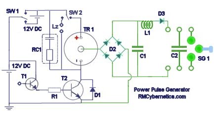
The diagram illustrates a series connection of cell diode capacitors, each rated for an increasing voltage of 300 V. This configuration generates a high DC voltage supply of 40 kV, which can be utilized for various experimental applications. With...
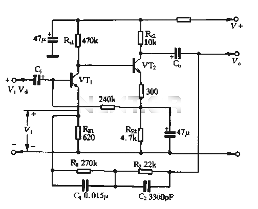
The feedback voltage (Vf) is derived from the output voltage (Vo) through an EQ network. The input voltage (Vf) is related to the subtraction process, yielding a pure input voltage for the circuit, which is associated with the tandem...
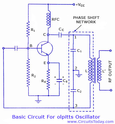
Colpitts oscillator circuit diagram and theory. Colpitts oscillator frequency equation. Colpitts oscillator using transistor. Colpitts oscillator using op-amp. The Colpitts oscillator is a type of electronic oscillator that generates sine waves and is widely used in various applications such as...
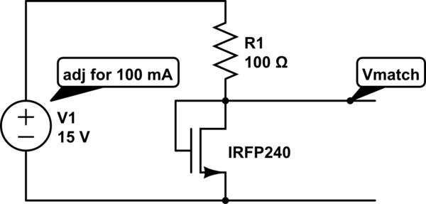
The unit is designed to drive an 80V/10A motor. The current matching circuit is utilized, but there is uncertainty regarding the appropriateness of the MOSFET selection for this application. The circuit for driving an 80V/10A motor typically requires careful consideration...
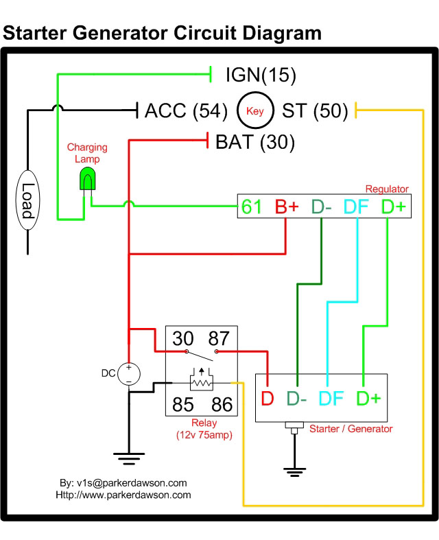
Circuit diagrams for both a Bosch and a Delco-Remy Starter-Generator are available, noting that the circuits differ. Due to a computer crash, the original diagrams and the associated email address were lost. However, in May 2004, both the email...
This is a highly sensitive touch plate circuit utilizing the NE555 timer IC, which activates a buzzer when a person touches the metal plate or hovers their hand above it. Compared to previously published touch control switch circuits, this...