
Frost Detector Temperature Sensor Circuit
The circuit's design integrates an LM35CZ temperature sensor, which is a precision device for measuring temperature in a range suitable for detecting freezing conditions. The output voltage of the LM35CZ is directly proportional to the temperature, allowing for straightforward interpretation of the readings. The LM35's compatibility with a single-ended power supply simplifies the circuit, making it easier to implement in battery-operated applications.
The inclusion of a resistor (R2) to facilitate the measurement of negative temperatures is a critical design choice, enabling the sensor to operate effectively below 0 °C by connecting it to a negative voltage. This allows the circuit to detect freezing conditions, which is essential for applications such as frost alarms.
The comparator circuit is a vital component, providing a mechanism to trigger an LED indicator when the temperature falls below the freezing point. The use of a diode (D1) to create a negative reference voltage for the comparator's non-inverting input is an innovative solution that ensures the circuit can respond accurately to slight variations in temperature.
Hysteresis is implemented to prevent rapid cycling of the LED indicator, which can occur due to minor fluctuations around the freezing point. By utilizing resistors R3 and R4 along with diode D2, the circuit ensures that once the LED is activated, it remains illuminated until the temperature rises significantly, thereby avoiding unnecessary power consumption and providing a reliable indication of frost conditions.
The power management features are well thought out, with the circuit designed to minimize current draw during standby operation. This is crucial for battery-powered applications, ensuring long operational life even under continuous monitoring conditions. The choice of a low-current LED further contributes to the efficiency of the design, allowing for prolonged use without frequent battery replacement.
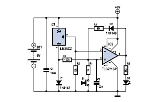
Overall, this temperature sensing and frost detection circuit represents an effective solution for monitoring freezing conditions, suitable for various applications where temperature monitoring is critical. The careful selection of components and design considerations ensures accuracy, reliability, and efficiency, making it a valuable tool in frost detection systems.To know whether it is freezingyou only need tomeasure the temperature. This has to be done accurately, of course, and therefore we need to choose atemperature sensorthat we have some confidence in. The choice has again been made for a type that we have already used in many previous Elektor circuits, theLM35CZ(-40 to 110 °C).
Thissensor is not exp ensiveand generates an output voltage that is proportional to thetemperature in degrees Celsius(10 mV/ °C). AnLM35is normally powered from a single-ended power supply and 0 °C corresponds to an output voltage of 0 V.
It is therefore not possible to measurenegative temperatureswith an LM35 in the standard application circuit. It is however possible to measure negative temperatures if its output is connected to a negative supply voltage via a resistor.
There needs to be a current of 50 A through this resistor (R2 in the schematic). We only need todetect the freezing pointwith this circuit. That is why there is acomparatorafter thetemperature sensor, which turns an LED on if the temperature has dropped below 0 °C during the course of the night. To ensure that the comparator operates properly it is necessary that the measurement value can become slightly more negative with respect to the input.
To solve this problem, a diode (D1) has been connected in series with the ground connection of the LM35. The voltage drop across D1 (because of the small current through the LM35 this is only 0. 47 V) acts as `negative` power supply. Since the non-inverting input of comparatorIC2 is connected via R3 to the anode of D1 it functions as the 0 °C-reference level for the comparator.
connecting the bias-select input (pin 8) to the power supply voltage. There is no need for the detector to be fast and it will therefore work well with the opamp operating in its most economical mode. LED D3 provides thefrost indication. It is the intention that the LED stays on once the temperature in the room drops below freezing or when it has been below freezing.
To realise this, an asymmetric hysteresis is created with the aid of R3, R4 and D2. The instant that the output goes high, the non-inverting input goes more positive via D2 and R4, and the output therefore stays high. The temperature would now have to increase to more than about 30 ° before the LED will go out by itself.
In practice this probably means that it is summer and that it is not likely to freeze anyway. If need be, the hysteresis can be increased by increasing the value of R3. Capacitor C2 is added to make sure that the LED remains off (the circuit is reset) when the power supply is connected. The non-inverting input of the opamp is briefly connected to ground and the output is therefore low. R1 and S1 are only required if the circuit needs to be reset when the battery is connected. Instead of S1 you could also use a power supply switch or even just simply disconnect the battery for a moment.
Since the circuit is assumed to be powered from a battery there was a conscious effort to minimise the power consumption. The current consumption of the prototype, at a power supply voltage ranging from 6 to 9 V, was less than 120 A.
When the LED is on, the current consumption rises to only 1 mA at 6V and 1. 8 mA at 9V, because a low current LED is used. In our prototype we used a green, low-current LED. If four AA penlight batteries (with a capacity of about 2 Ah) are used, then the circuit will run for about two years in standby mode. When the LED is on this is considerably shorter, of course (about two months, this is easily long enough to run through a severe winter period).
A standard 9-V battery will also last a single winter, provided you frequently check whether the LED is on. Finally, a comment about the TLC-271CP used here. The version with the C-suffix is specified for an operating range from 0 to 70 °C, but will continue to work atlower temperatures, particularly considering that theIC is n
🔗 External reference
Related Circuits
This circuit is one of the most basic and popular sensor modules. In electronics, this sensor is analogous to human visual senses and can be used. The described sensor module serves as a fundamental component in various electronic applications, emulating...
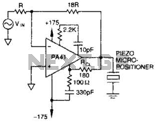
The PA41 from Apex Microtechnology is utilized to drive a piezoelectric micropositioner. The drive voltage is less than 20 V peak-to-peak at the input. The PA41 is a high-performance power amplifier designed specifically for driving piezoelectric devices, which require precise...
A unit that is often very useful for isolating two stages in sound circuits. This circuit incorporates an amplification unit with a gain of X1. It employs only local negative feedback rather than total negative feedback, resulting in very...
The NE5532 preamplifier is widely recognized for its excellent performance. It is now being utilized as a small power amplifier. While the general operational amplifier (op-amp) circuit remains similar, there are notable changes in some resistors and capacitors, leading...
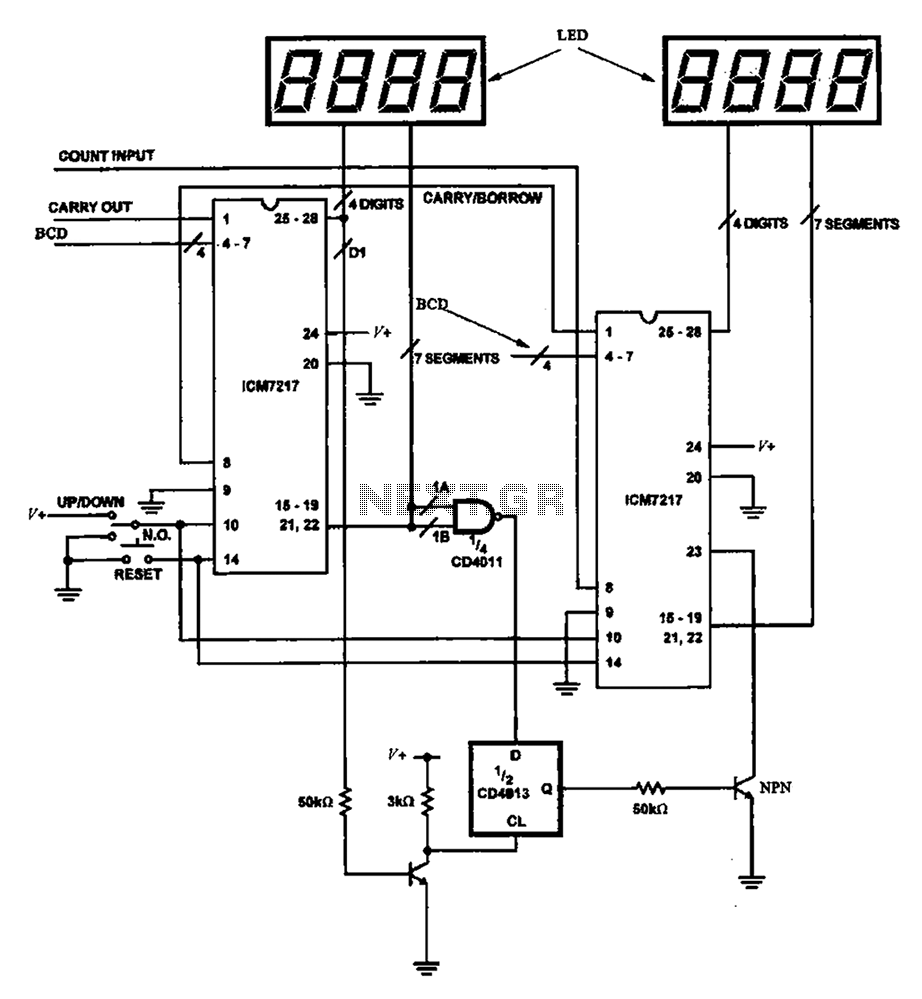
Figure 8 illustrates a potential digital counter circuit. This circuit employs two ICM7217 integrated circuits, with each controlling four digital display tubes. The digital counter circuit primarily utilizes the ICM7217, a highly integrated chip designed for driving seven-segment displays. Each...
Touch controls are not only utilized for switching devices on or off but can also manage various functions. A notable example is the TV remote control. When it is crucial to maintain activated functions for an extended period, employing...
Warning: include(partials/cookie-banner.php): Failed to open stream: Permission denied in /var/www/html/nextgr/view-circuit.php on line 713
Warning: include(): Failed opening 'partials/cookie-banner.php' for inclusion (include_path='.:/usr/share/php') in /var/www/html/nextgr/view-circuit.php on line 713