
8-bit digital counter circuit
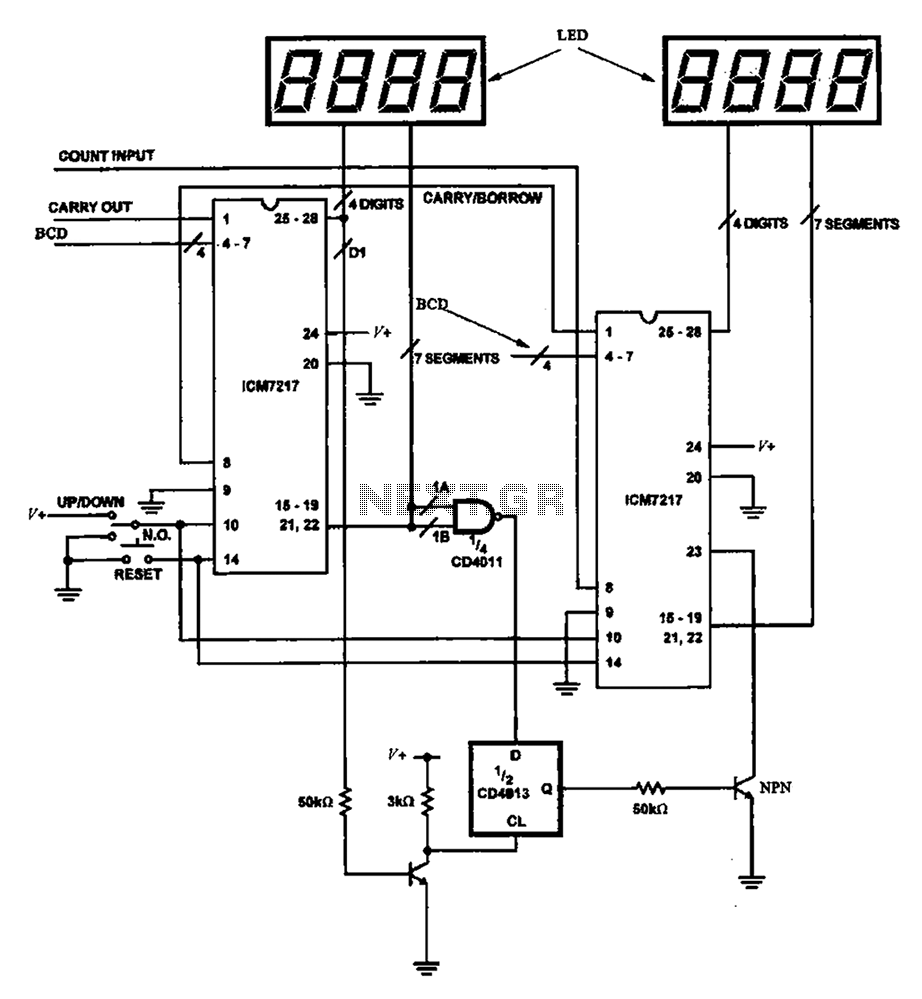
The digital counter circuit primarily utilizes the ICM7217, a highly integrated chip designed for driving seven-segment displays. Each ICM7217 can control up to four digits, making it suitable for applications requiring a visual representation of numerical values. The circuit design typically includes a clock input, which dictates the counting speed, and reset functionality to initialize the count.
In this configuration, the two ICM7217 chips are interconnected to expand the counting capability to eight digits. The clock signal can be generated using a simple oscillator circuit, often implemented with a 555 timer or a microcontroller, providing precise timing for the counting operation. The output from each ICM7217 is connected to the respective anodes of the four-digit displays, while the common cathodes are grounded, allowing for the proper illumination of the segments.
Additional components in the circuit may include resistors for current limiting, ensuring that the LED segments do not draw excessive current, which could lead to damage. Capacitors may also be incorporated for debouncing the clock signal to prevent false triggering due to noise.
The overall layout of the circuit should be carefully designed to minimize interference and ensure stable operation. Proper grounding and power supply decoupling are crucial to maintain the performance of the ICM7217 chips, especially in environments with fluctuating power conditions.
This digital counter circuit finds applications in various fields, including digital clocks, scoreboards, and other devices requiring numerical display functionality. Its straightforward design and effectiveness make it a popular choice among electronics enthusiasts and professionals alike.8 shows a possible digital counter circuit. This circuit uses two ICM7217 integrated chips each control four digital tube.
Related Circuits

The Pyro Propeller Clock POV schematic is relatively straightforward. It consists of three primary components: the power supply utilizing a 7805 voltage regulator, the LED output control managed by a PIC18F252 microcontroller and a 74LS373 latch, and the 'home'...
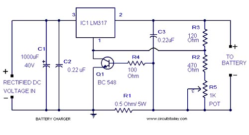
A simple lead-acid battery charger circuit with a diagram and schematic using the IC LM317, which provides the correct battery charging voltage. This lead-acid battery charger should be supplied with an input of 18 volts to the IC. The lead-acid...
Construct a low-power FM transmitter using surface-mount devices (SMD) that can be received by a standard FM radio. The proposed low-power FM transmitter circuit utilizes surface-mount devices (SMD) to achieve compactness and efficiency. The primary components of the circuit include...
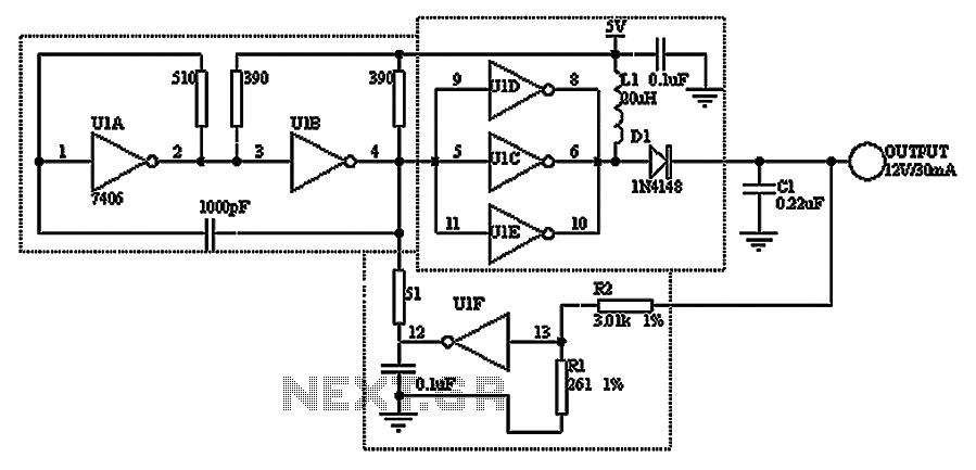
A TTL hex inverter circuit can function as a DC/DC converter, converting 5V to 12V. This circuit encompasses all necessary functionalities for DC/DC conversion. It relies on a TTL switching threshold voltage regulator. The components U1A and U1B form...
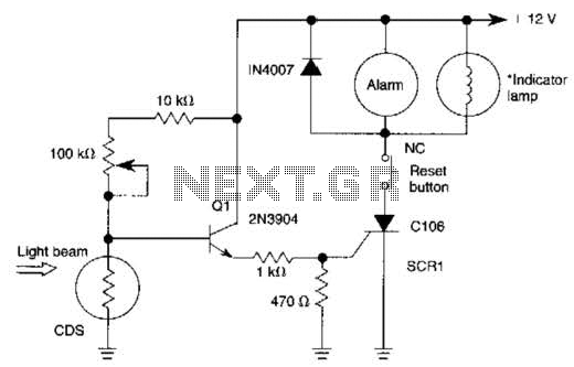
When the light beam that falls on the CDS photocell is interrupted, the transistor (EN3904) conducts, triggering SCR1 (CI06) and activating the alarm bell. SI resets the SCR. The alarm bell should be a self-interrupting electromechanical type. The lamp...
Ensure that connections are verified against the circuit diagram and schematic provided below. This can be utilized while following the tutorial video. The circuit diagram serves as a crucial reference for accurately assembling electronic components in a project. It illustrates...
Warning: include(partials/cookie-banner.php): Failed to open stream: Permission denied in /var/www/html/nextgr/view-circuit.php on line 713
Warning: include(): Failed opening 'partials/cookie-banner.php' for inclusion (include_path='.:/usr/share/php') in /var/www/html/nextgr/view-circuit.php on line 713