
Touch Volume Control Circuit
The touch volume controller circuit operates effectively by utilizing a high-impedance input configuration of an operational amplifier, which allows for sensitive detection of touch inputs. The integration function of the op-amp facilitates the conversion of touch inputs into a corresponding voltage output, which is crucial for applications requiring precise volume control or similar functions. The design incorporates capacitors that serve dual purposes: they stabilize the circuit by preventing oscillations and contribute to the retention of the output voltage level when the touch sensors are disengaged.
In practical applications, the touch volume controller can be integrated into various electronic devices, enhancing user interaction through touch sensitivity. The ability to replace touch sensors with push-button switches adds flexibility to the design, catering to different user preferences and operational environments. Furthermore, the moisture-proof enclosure recommendation underscores the importance of protecting the circuit from environmental factors that could exacerbate the voltage drift issue, thus extending the operational reliability of the device.
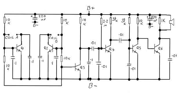
Overall, this touch volume controller circuit provides a versatile solution for modern electronic devices, balancing the need for user-friendly interfaces with the challenges of maintaining consistent performance over time.Touch controls are not only used to switch devices on or off. They can also be used to control different functions. One good example is the TV remote control. If it is very important to keep the activated functions for a long period of time, it is always better to use a digital memory system. However, if small drifts in the control status is accep table, a simple analog design can be used to memorize the status. The touch volume controller is one such analog memory touch control switch. The main function centers mostly on the IC1. It is an opamp configured as an integrator with a high impedance input. If sensor 1 is touched, the capacitor C2 charges through the skin resistance and voltage at the output of IC1 decreases linearly until it reaches zero volt. Touching the other sensor (sensor 2) will produce the opposite result: the voltage at the pin 6 of IC1 will increase linearly until it reaches the power supply level.
The special function of this touch volume control circuit is that after moving your finger away from the sensor(s), the output voltage of IC1 stays at that level. This voltage value is memorized by C2. This analog memory however has a problem in long time periods: The voltage value drifts away by 2 % per hour due to the unavoidable current leak in the capacitor.
To improve this situation, it is highly recommended to put this circuit in a moisture proof box. This touch volume controller circuit has a wide application range. It can be used in devices where a potentiometer can be controlled through voltage levels. The touch sensors can alse be replaced with conventional push button switches. The capactiors C1 and C4 are very important in the circuit: they prevent the IC1 from oscillating. Simultaneously closing both switches will not damage the circuit. 🔗 External reference
Related Circuits
By adjusting the oscillators so their frequencies are very nearly the same, the difference between them is made audible as a beat note. This beat note changes slightly when the search loop is moved over or near to a...
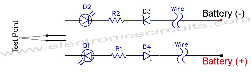
12V Vehicle Electrical Wiring Tester Circuit. This tester is useful for checking vehicle electrical circuits. Two LEDs indicate whether the circuit is live or not. The 12V vehicle electrical wiring tester circuit is designed to provide a simple yet effective...
To sense and control the current in stepping motors and other similar devices, a linear integrated circuit such as the L6506 can be utilized. This chip set enables the formation of a constant current output. The L6506 is a versatile...
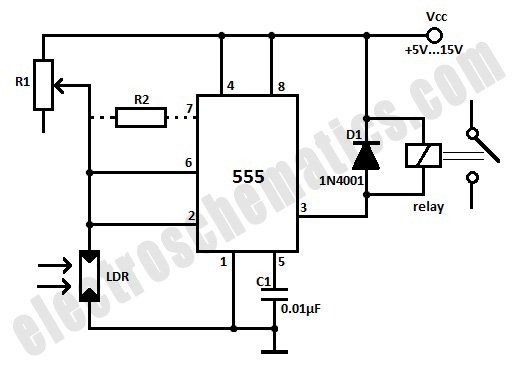
This light-activated relay circuit utilizes the 555 timer integrated circuit (IC) and a light-dependent resistor (LDR) to create a light-sensitive relay suitable for applications such as intruder alarm systems or automatic lamp control at sunset and sunrise. The potentiometer...
You can play this game alone or with your friends. The circuit comprises a timer IC, two decade counters and a display driver along with a 7-segment display. The game is simple. As stated above, it is a scoring...
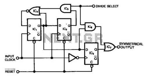
This circuit generates a symmetrical waveform by dividing the input frequency by either 2 or 3. The Divide Select input governs the division factor. When the Divide Select input is high, flip-flops IC1 and IC2, along with the associated...
Warning: include(partials/cookie-banner.php): Failed to open stream: Permission denied in /var/www/html/nextgr/view-circuit.php on line 713
Warning: include(): Failed opening 'partials/cookie-banner.php' for inclusion (include_path='.:/usr/share/php') in /var/www/html/nextgr/view-circuit.php on line 713