
Fuel-cell battery tester
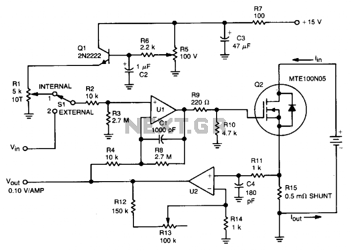
The circuit operates by utilizing a dynamic load configuration that allows for precise control over the current drawn from the fuel cell or battery under test. The TMOS Power FET (Q2) acts as the primary switching element, providing efficient operation at the required current levels. When switch SI is set to position 1, the emitter follower configuration formed by Q1 and R1 establishes a stable current reference. This configuration is crucial for maintaining the desired load current without manual intervention.
In position 2, the circuit can accept an external voltage signal to modulate the load current, providing flexibility for various testing scenarios. The operational amplifier U1 plays a critical role in regulating the load current. It receives feedback from the voltage drop across R15, which is directly proportional to the current flowing through the load. The feedback loop ensures that any variations in load current are corrected promptly, maintaining a constant current output to the fuel cell or battery.
The feedback mechanism is designed such that any increase or decrease in the voltage across R15 results in a corresponding adjustment in the output of U1. This maintains the load current at a constant value, which is essential for accurate testing of the device under evaluation. The adjustment potentiometer R13 allows for calibration of the feedback sensitivity, enabling the user to fine-tune the relationship between the voltage and current in the system.
The VOUT point serves as a monitoring output, providing a means to observe the performance of the circuit during operation. This allows for real-time assessment of the load conditions and the overall health of the fuel cell or battery being tested. The design is optimized for high current applications, making it suitable for rigorous testing environments where reliable performance and accurate measurements are paramount.This circuit was designed for testing fuel cells, but it could also be used for testing batteries under a constant current load. It provides a dynamic, constant current load, eliminating the need to manually adjust the load to maintain a constant load.
For fuel cell application, the load must be able to absorb 20-40 A, and since a single cell develops only 0.5 to 1.0 V, bipolar power devices (such as a Darlington) are impractical. Therefore, this dynamic load was designed with a TMOS Power FET (Q2). With switch SI in position 1, emitter follower Ql and Rl establish the current level for the load. In position 2, an external voltage can be applied to control the current level. Operational amplifier Ul drives TMOS device Ql, which sets the load current seen by the fuel cell or battery. The voltage drop across R15, which is related to the load current, is then applied to U2, whose output is fed back to Ul.
Thus, if the voltage across R15 would tend to change, feedback to the minus input of Ul causes that voltage (and the load current) to remain constant. Adjustment of R13 controls the volts/amp of feedback. The V0UT point is used to monitor the system. 🔗 External reference
Related Circuits
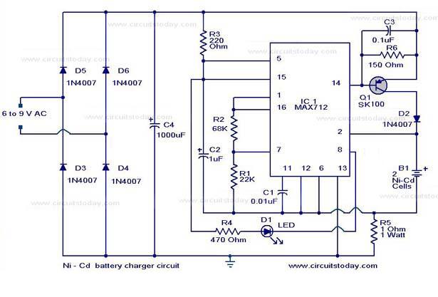
The following circuit illustrates a super fast Ni-Cd battery charger. It is based on the IC MAX 712 and is designed to charge a Ni-Cd battery at a rate of 300 mA. The circuit utilizes the MAX 712 integrated circuit,...
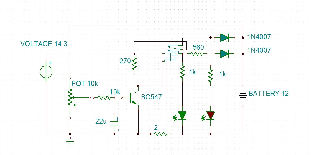
Using a transistor will not yield accurate results, and the adjustment process can become quite tedious. The circuit is technically correct; if the tripping point can be adjusted properly, it may function as intended. Vinod states that he created...
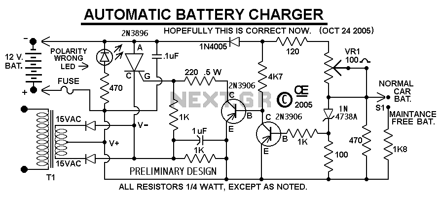
This Charger Can't be used as a Power Supply, Without having a battery in place. The Battery MUST be Connected to get power out. Note: This Charger Features a Reverse polarity Indicator. Instructions: Before plugging this charger into the...
This simple circuit makes it possible to monitor the charging process to a higher level. If you need more information then check out the LM3914 Datasheet. Final adjustments are simple and the only thing needed is a digital voltmeter...
This design is based on one published by Milan Lulic in the German magazine elektroModell. Mr. Lulic's design is for surface mount technology (SMT) construction, whereas mine uses standard off-the-shelf components, and is therefore better suited to construction by...
This is a simple NiCd battery charger powered by solar cells. A solar cell panel or an array of solar cells can charge a battery at more than 80% efficiency. The described circuit functions as a basic NiCd battery charger...