
Full Bridge Inverter with MOSFET and IR2110 gate driver
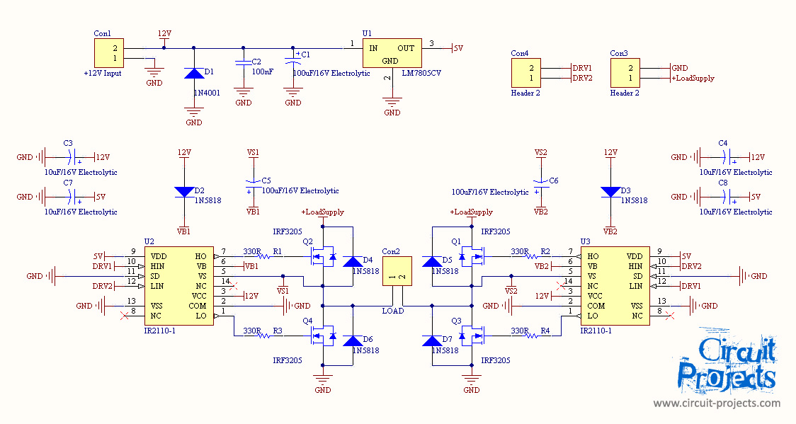
The grid-connected inverter is a crucial component in renewable energy systems, particularly in solar photovoltaic (PV) applications, where it converts the direct current (DC) generated by solar panels into alternating current (AC) that can be fed into the electrical grid. The full bridge inverter configuration is favored for its efficiency and ability to provide a high-quality output waveform.
In a full bridge inverter circuit, four switches (typically MOSFETs or IGBTs) are arranged in a bridge configuration. The operation involves alternating the conduction states of these switches to produce the desired AC output voltage. The control strategy is essential for achieving a sinusoidal output waveform and maintaining grid synchronization. Techniques such as pulse width modulation (PWM) are commonly employed to regulate the output voltage and frequency.
The inverter must also include protective features such as overcurrent protection, voltage clamping, and thermal management to ensure reliable operation. Additional components such as inductors and capacitors may be incorporated to filter the output waveform and reduce harmonic distortion.
Furthermore, the inverter should be designed to comply with grid connection standards, which may include requirements for anti-islanding protection, power factor correction, and maximum power point tracking (MPPT) to optimize energy harvesting from the solar panels.
Overall, the design of a grid-connected full bridge inverter involves a careful selection of components, control strategies, and protective measures to ensure efficient and safe integration with the electrical grid.This is my first post here, i need help on my final year project to make a grid connected inverter. For the full bridge inverter circuit i planned to.. 🔗 External reference
Related Circuits
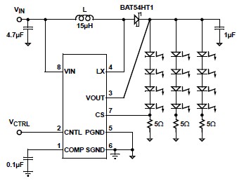
A simple white LED driver schematic can be created using the EL7513 constant current boost regulator, which is specifically designed for driving white LEDs. This driver can manage 4 LEDs in series or up to 12 LEDs in a...
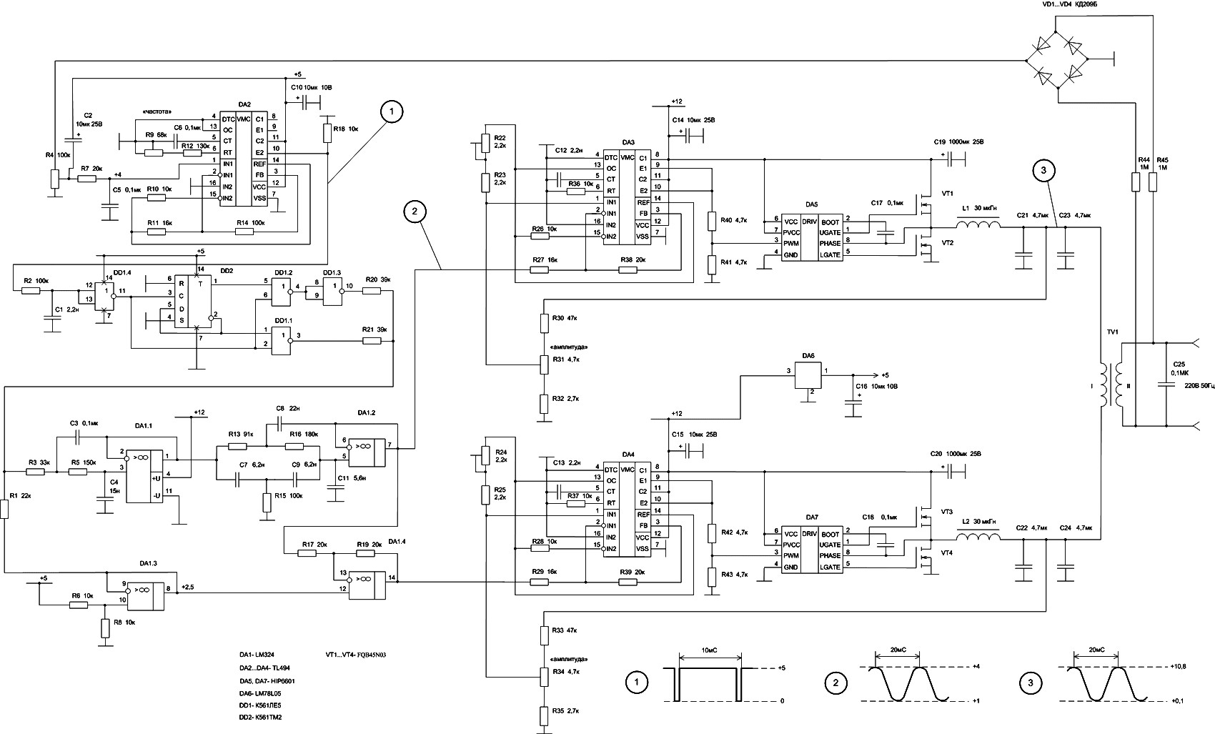
In DA3, DA5, VT1, and VT2, the first channel of the VLF Class D amplifier is assembled. The second channel is constructed using DA4, DA7, VT3, and VT4. Antiphase sine waves in the VLF range are formed at the...
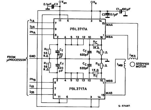
The PBL3717A stepper motor driver is a monolithic integrated circuit that controls and drives one phase of a bipolar stepper motor utilizing chopper control for phase current regulation. Current levels can be selected in three increments using two logic...
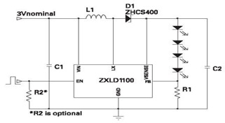
The ZXLD1100 is a PFM flyback DC to DC boost converter that operates in discontinuous mode. The following circuit diagram illustrates the configuration of four LED drivers for handset LCD backlighting using this device. The ZXLD1100 is designed to...
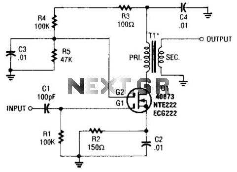
A MOSFET is utilized as a wideband buffer amplifier. T1 is wound on a toroid of approximately specified diameter, using material suitable for the frequency range, typically between 1 MHz and 20 MHz. The turns ratio should be approximately...
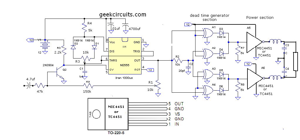
This document presents an improvised circuit model designed to eliminate unwanted DC offset voltage from the output, which affects previously discussed circuits. All prior circuits were intended as low-power Class D amplifier sources suitable for driving headphones through a...