
Full on transistor/fet curve tracer

The proposed electronic circuit design aims to create a versatile curve tracer that can analyze and visualize the characteristics of various semiconductor devices. The core of the circuit is based on Metzger's original curve tracer schematic, which utilizes a combination of resistors, capacitors, and transistors to generate the necessary voltage and current profiles for testing.
The adaptation to include an Analog-to-Digital Converter (ADC) is critical for digitizing the analog signals produced during the testing process. This ADC will convert the voltage and current readings from the circuit into a digital format suitable for processing and display. The output will be directed to a 320x256 ELD (Electroluminescent Display) panel, allowing for real-time visualization of the device characteristics being tested. The ELD panel will provide a clear and detailed representation of the curves generated by the device under test.
In addition to visual output, the circuit will incorporate a serial output interface. This feature will enable the transfer of critical data, including base current, collector current, and collector voltage, to a computer for further analysis. The data can be organized into a spreadsheet format, facilitating detailed examination and record-keeping.
The design will initially focus on testing NPN transistors, followed by PNP transistors, and will ultimately extend to Field-Effect Transistors (FETs). This phased approach allows for systematic development and testing of the circuit's capabilities. Future enhancements may include additional functionalities, such as automated testing sequences or expanded measurement ranges, to further improve the utility of the curve tracer.
Overall, this project represents an innovative approach to modernizing a classic electronic circuit, combining historical design principles with contemporary digital technology to enhance the analysis of semiconductor devices.Well since I learn fastest by doing (not exactly unique I guess) time to start my next trick. Adapting one of the many curve tracer schematics, probably Metzger`s circuit from the early `70s with modifications to an ADC capture system and output to a 320*256 ELD panel. (Because I have one to play with) And also add a serial output to enable transfer to a spread sheet of base current, collector current and collector voltage.
NPN first, followed by PNP and then FETs. May add the ability to run.. 🔗 External reference
Related Circuits
A fully parametric tube equalizer (EQ) design aims to merge two schematics into one. The goal is to create a tube-based gyrator section with adjustable Q, frequency, and gain while utilizing integrated circuits (ICs) for the input and follower...
A simple test circuit to fault find audio and radio equipment. Can be used to inject a square wave signal, rich in harmonics, or used with headphones as an audio tracer. A single pole double throw switch is used...
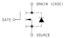
When the case temperature reaches 250°C, the device must be derated to maintain a maximum case temperature of 1500°C, ensuring that the junction temperature remains below the maximum permissible limit. This pertains to MIL-PRF-19500/543; Semiconductor Device, Transistor, Field Effect,...
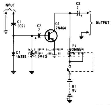
In this circuit, C1, D1, and R1 form an envelope detector. C2 couples audio to the base of Q1. R2 can be adjusted for the desired gain. The circuit under discussion utilizes an envelope detector, which is a fundamental component...
A simple test circuit to fault-find audio and radio equipment. It can be used to inject a square wave signal, rich in harmonics, or used with headphones as an audio tracer. This test circuit is designed to assist in diagnosing...
The LM3886 is an improved version of the LM3875. Key features of the LM3886 include a maximum output power of 68W RMS and 108W peak, with a total harmonic distortion (THD) of 0.03% at 60W. The LM3886 is a high-performance...