
signal tracer and injector
This test circuit is designed to assist in diagnosing faults in audio and radio equipment by providing a reliable method of signal injection. The circuit primarily generates a square wave signal, which is characterized by its sharp transitions and rich harmonic content. This feature allows for effective testing of the frequency response and linearity of audio devices, as the harmonics can reveal distortion and other anomalies in the equipment under test.
The circuit typically includes a function generator or an oscillator that produces the square wave output. This output can be connected to various points within the audio or radio circuit to evaluate performance. Additionally, the circuit may incorporate an adjustable amplitude control to vary the signal strength, ensuring compatibility with different devices and preventing damage to sensitive components.
For audio tracing, the circuit can be adapted to include a headphone output. This allows the technician to listen to the audio signals directly, facilitating the identification of faults such as intermittent connections, noise, or distortion. The use of headphones also provides a convenient way to monitor the audio signal without requiring additional equipment.
In summary, this simple test circuit serves as an essential tool for audio and radio equipment troubleshooting, offering both signal injection capabilities and audio monitoring through headphones. Its design emphasizes versatility and ease of use, making it suitable for both professional technicians and hobbyists alike.A simple test circuit to fault find audio and radio equipment. Can be used to inject a square wave signal, rich in harmonics, or used with headphones as an audio tracer.. 🔗 External reference
Related Circuits
This simple circuit generates narrow pulses at about 700-800Hz frequency. The pulses, containing harmonics up to the MHz region, can be injected into audio or radio-frequency stages of amplifiers, receivers and the like for testing purposes. A high-pitched tone...
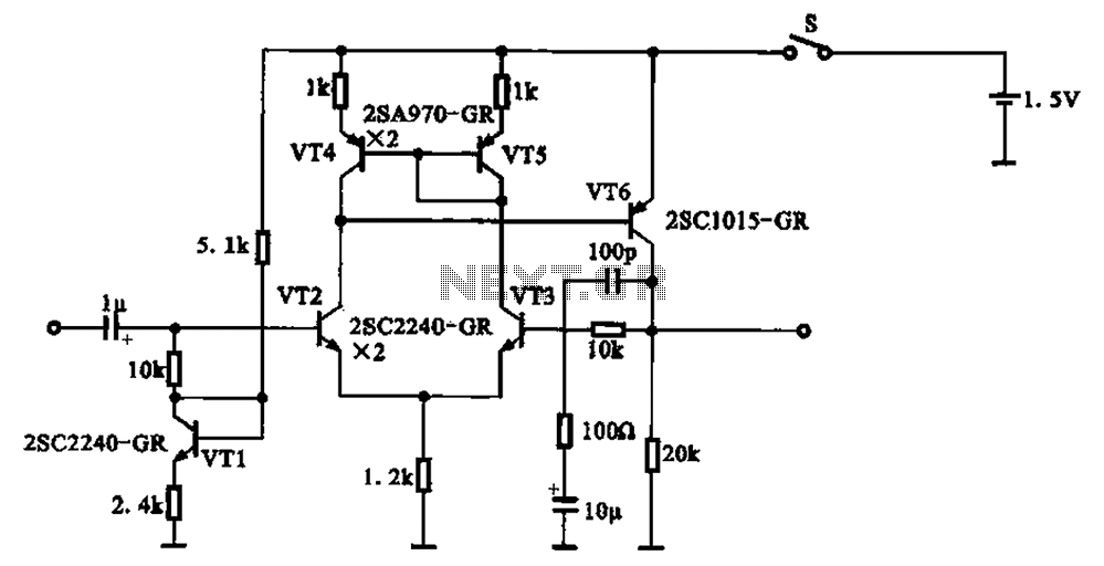
A 1.5V-powered microphone signal amplifying circuit is designed with a power supply for the microphone signal amplification. The circuit primarily consists of a differential amplifier formed by transistors VT2 and VT3. Additionally, VT6 functions as a common emitter voltage...
An IR remote control is a widely used device found with televisions, VCRs, and home theaters. It can also be utilized to control personal devices such as lights and air conditioning. Remote controls operate using infrared (IR) light, which...
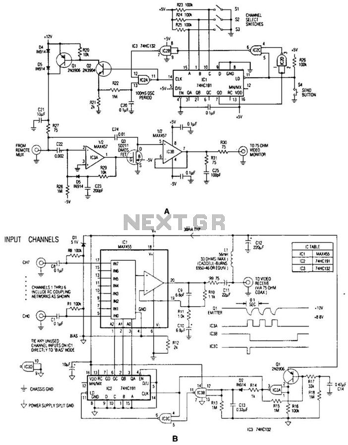
In the video system illustrated in Figures A and R, a single coaxial cable transmits power to a remote location, selects one of eight video channels, and returns the selected signal. This system can choose from several remote surveillance...
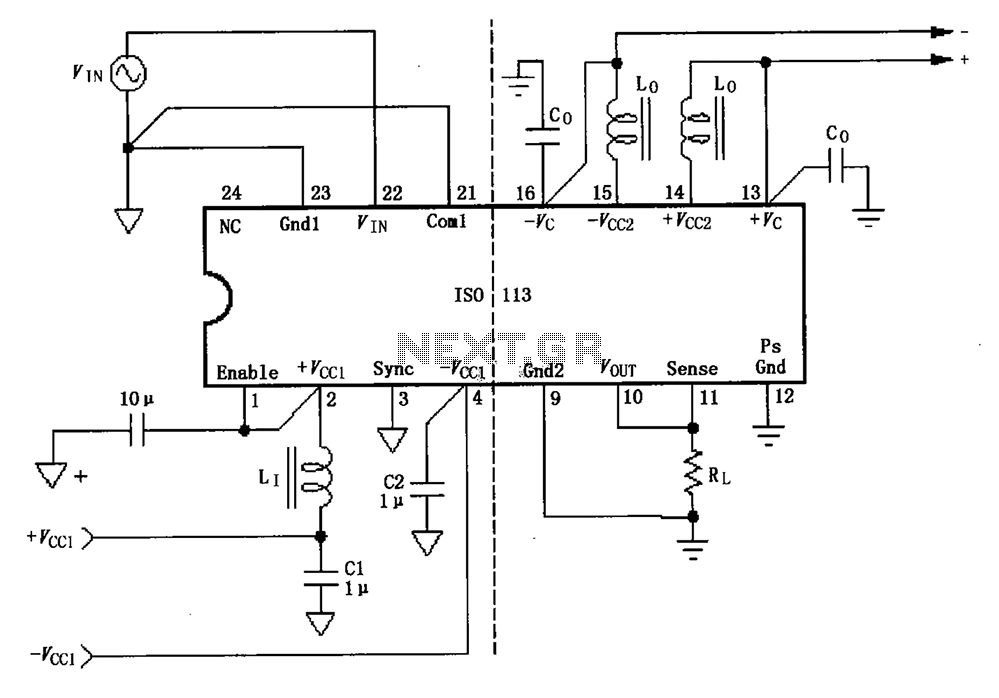
The basic connection circuit for the ISO113 signal and power supply is illustrated. Each power supply terminal must include a bypass filter. If the output current from the isolated power supply exceeds 15mA, it is advisable to utilize an...
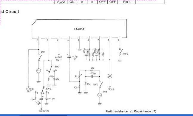
The LA7051 is a video and audio signal processor integrated circuit (IC) designed for UHF band RF modulation. It performs functions such as audio frequency modulation, video clamping, and white clipping. The LA7051 IC is engineered to facilitate the modulation...