
Full-wave Phase Control Using Lower Voltage DIAC

The DIAC is a semiconductor device that operates in a bidirectional manner, allowing current to flow in both directions once the applied voltage surpasses a specified threshold known as the breakdown voltage. This characteristic makes the DIAC particularly useful in various applications, including light dimmers, motor speed controls, and over-voltage protection circuits.
A typical DIAC consists of four layers of semiconductor material, forming a p-n-p-n structure. When the voltage across the device exceeds the breakdown voltage, the DIAC transitions from a non-conductive state to a conductive state, allowing current to pass through. This transition is often used to trigger other components in a circuit, such as triacs or thyristors, which can control larger loads.
In practical applications, the DIAC is often used in conjunction with other components such as resistors and capacitors to form timing circuits or to create specific trigger conditions. The device is characterized by its ability to provide a sharp switching action, making it suitable for applications where precise control of voltage and current is essential.
The DIAC is typically packaged in a variety of forms, including through-hole and surface-mount options, allowing for flexibility in circuit design. Its robust nature and ability to withstand high voltages make it a reliable choice for many electronic applications.The DIAC, or diode for alternating current, is a trigger diode that conducts current only after its breakdown voltage has been exceeded momentarily. Most DIAC.. 🔗 External reference
Related Circuits

The precision Phase Locked Loop (PLL) in this circuit operates similarly to a basic PLL, but with several enhancements. The flip-flops in the detector are equipped with a gate G1 to clear them, allowing for a faster response. The...
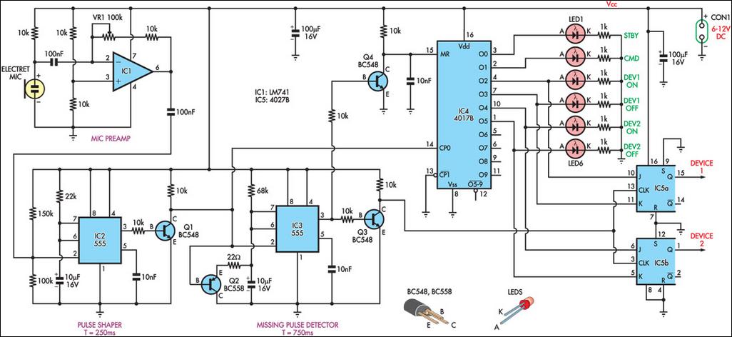
This circuit can switch two or more devices on and off in response to a series of rapid handclaps. The claps are detected by an electret microphone and amplified by a 741 operational amplifier (IC1). IC1 is configured as...
This continuity tester circuit allows for the examination of PCB track failures without the need to visually inspect the routing of the tracks, which can often be frustrating. The continuity tester circuit is designed to facilitate the detection of faults...
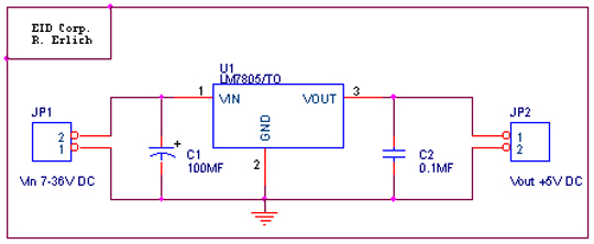
The LM78XX series is capable of delivering a current of up to 1A. For applications requiring up to 150mA, the 78LXX variant is suitable. This component features three terminals: an input terminal that can handle up to 36VDC, a...
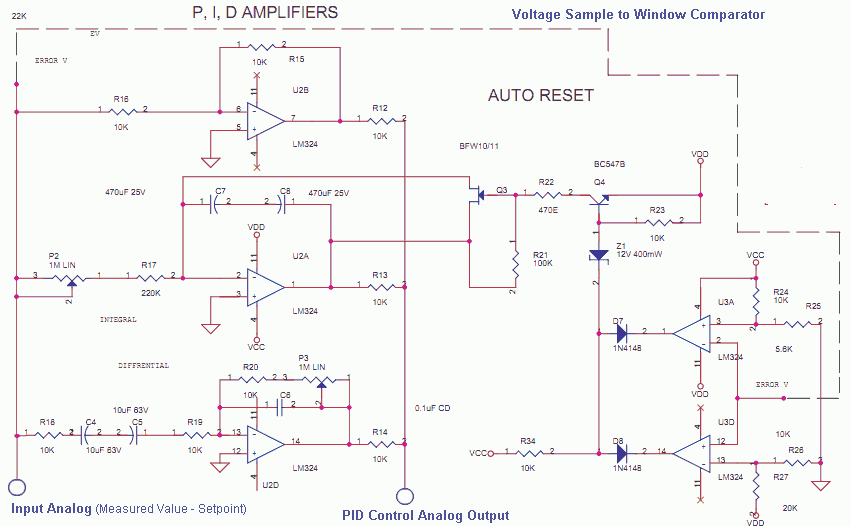
The Measured Value and the Setpoint are two inputs to a control system. The Measured Value is the amplified input from a transducer or sensor for a specific parameter that requires regulation, such as pressure or temperature. The Setpoint...

A voltage-controlled oscillator using the NE555. This circuit is commonly referred to as a voltage-to-frequency converter because the output frequency is altered by varying the input voltage. As previously noted, pin 5 serves as the voltage control terminal, which...