
Full-wave scr control

The circuit consists of an SCR, which is a semiconductor device used to control power. It is typically employed in applications requiring the regulation of electrical power to resistive loads, such as heaters or incandescent lamps. The full-wave control configuration allows for the SCR to conduct during both halves of the AC waveform, effectively providing smoother control of the load current.
The potentiometer R2 serves as an adjustable resistor that allows for fine-tuning of the load current. By adjusting R2, the user can vary the gate trigger voltage applied to the SCR, thereby controlling the timing of the SCR's conduction phase. When R2 is set to its minimum, R3 ensures that the load receives a minimum current, which is critical for applications where maintaining a baseline current is necessary for proper operation.
Resistor R3 plays a vital role in this circuit by limiting the current flow through the load when the SCR is conducting. It is crucial that R3 is chosen based on the specific characteristics of the load and the desired minimum current level. The resistor must be rated appropriately to handle the power dissipation that occurs during operation.
In addition to the SCR and resistors, diodes are included in the circuit to protect against back EMF and ensure proper functioning of the SCR. It is essential that the diodes have equivalent current and voltage ratings to that of the SCR to prevent failure due to overvoltage or overcurrent conditions.
Overall, this circuit design provides an effective means of controlling resistive loads with a single SCR while ensuring that the load current can be finely adjusted to meet operational requirements. Proper selection of components, particularly R2 and R3, as well as the diodes, is critical to the reliability and performance of the circuit.This circuit enables a single SCR to provide fullwave control of resistive loads. Resistor R3 should be chosen so that when potentiometer R2 is at its minimum setting, the current in the load is at the required minimum level Diodes should have same current and voltage rating as the SCR.
Related Circuits
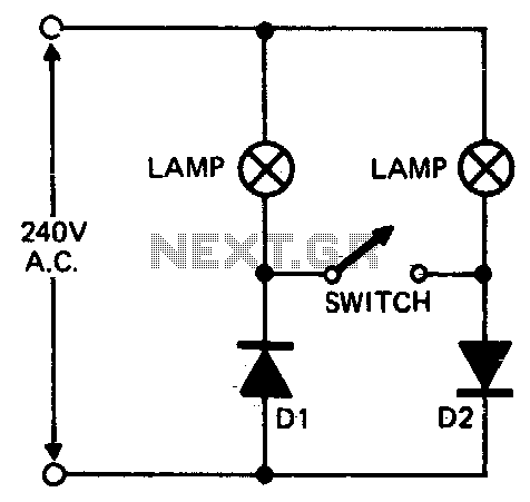
When setting up photographic floodlamps, it is sometimes desirable to operate the lamps at lower power levels until actually ready to take the photograph. The circuit allows the lamps to operate on half-cycle power when the switch is open...
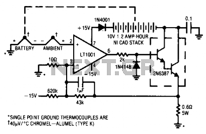
One effective method for rapidly charging Ni-Cad batteries without causing damage is to monitor the cell temperature and adjust the charge rate accordingly. This circuit employs a thermocouple for temperature measurement. A second thermocouple is used to negate the...
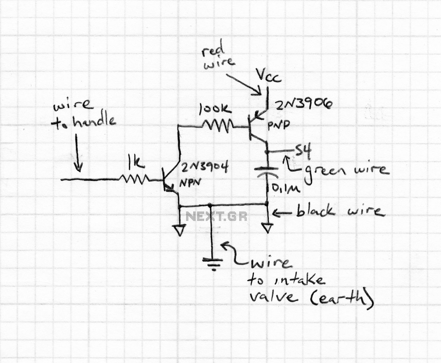
Upon entering the password, the application, in this case "LED," will illuminate. In this digital locking system project, the interfacing of a keypad and a 16x2 LCD with a microcontroller will be explored, along with the accompanying code. This...
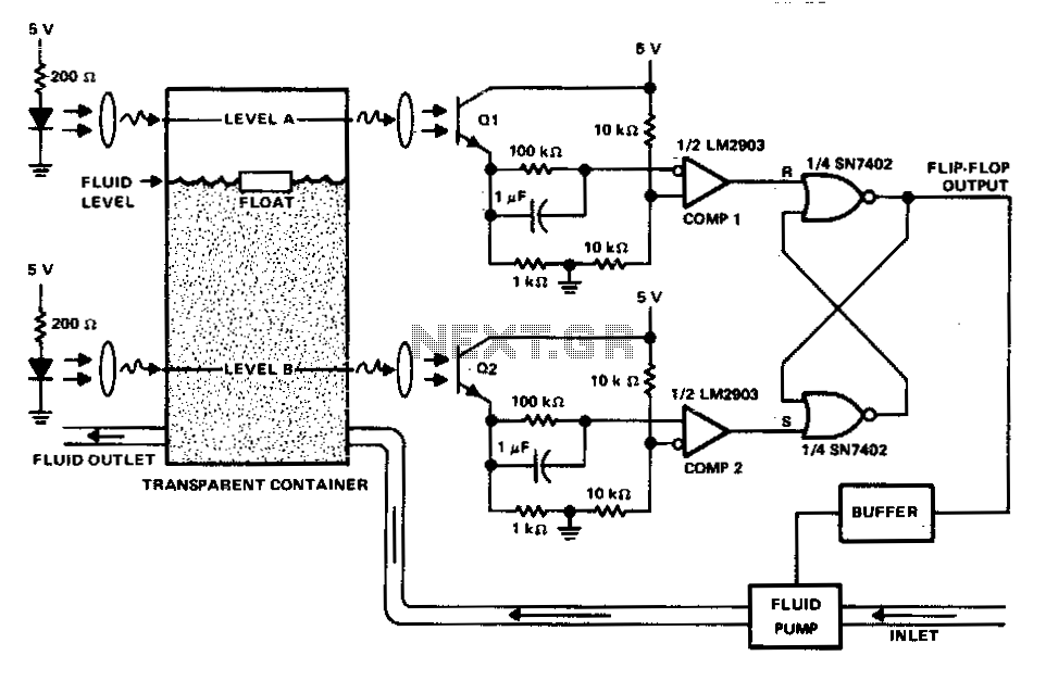
This circuit can be used to maintain fluid between two levels. Variations on this control circuit can be made to keep something that moves within certain boundary conditions. The described circuit functions primarily as a fluid level control system, designed...
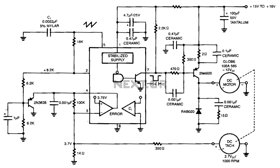
The NE5561 provides pulse-proportional drive and speed control based on DC tachometer feedback. This simple switching circuit consists of a 2N4920 PNP transistor with a commutation diode, which is used to deliver programmed pulse energy to the motor. A...
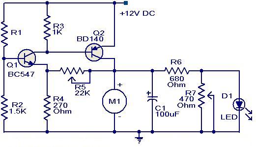
This circuit utilizes two transistors to control the speed of a 12 V DC fan based on temperature variations. A thermistor (R1) is used to sense the temperature. As the temperature rises, the base current of Q1 (BC 547)...