
Fully Automatic Emergency Light circuit
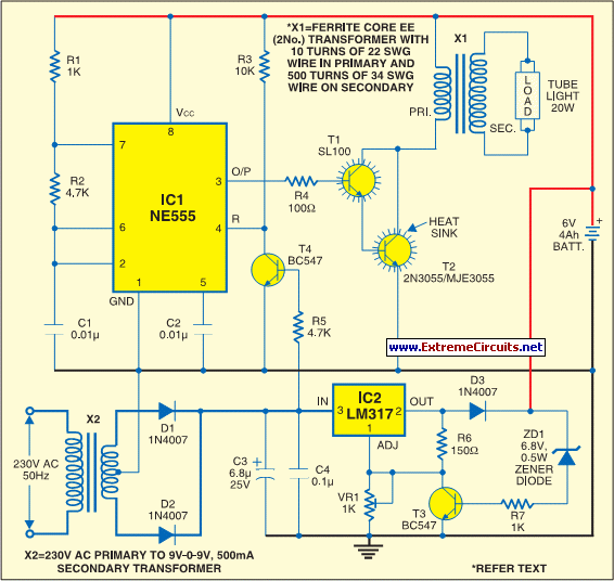
The inverter section of this circuit is designed to convert a DC input voltage into an AC output voltage. The NE555 timer, functioning as an astable multivibrator, continuously oscillates to produce a square wave signal at a frequency of 15 kHz. This square wave is crucial for driving the subsequent power amplification stage. The output from pin 3 of the NE555 is a square wave that toggles between high and low states, which is then amplified by the Darlington pair consisting of transistors SL100 and 2N3055. The Darlington configuration allows for high current gain, making it suitable for applications requiring substantial output power. The resistor R4 serves to limit the base current to the transistors, ensuring stable operation and preventing damage due to excessive current.
The charger section of the circuit is responsible for regulating the voltage supplied to a connected battery or load. The LM317 adjustable voltage regulator is employed for this purpose, allowing for precise control over the output voltage. The LM317 can provide a variable output voltage, typically ranging from 1.25V to 37V, depending on the external resistors used in the configuration. This flexibility makes the circuit suitable for various charging applications, accommodating different battery types and voltages.
Overall, this circuit effectively combines the inverter and charger functionalities, making it a versatile solution for powering AC loads while simultaneously providing a regulated DC charging capability. The design emphasizes efficiency and reliability, suitable for use in various electronic applications.The circuit can be divided into inverter and charger sections. The inverter section is built around timer NE555, while the charger section is built around 3-terminal adjustable regulator LM317. In the inverter section, NE555 is wired as an astable multivibrator that produces a 15kHz squarewave.
Output pin 3 of IC 555 is connected to the Darlington pair formed by transistors SL100 (T1) and 2N3055 (T2) via resistor R4.. 🔗 External reference
Related Circuits

The micro ampere meter presented here functions as a DC millivolt meter. It achieves full-scale deflection with a 0.1V input. The current to be measured flows through a known resistance R, and the voltage drop across this resistance is...
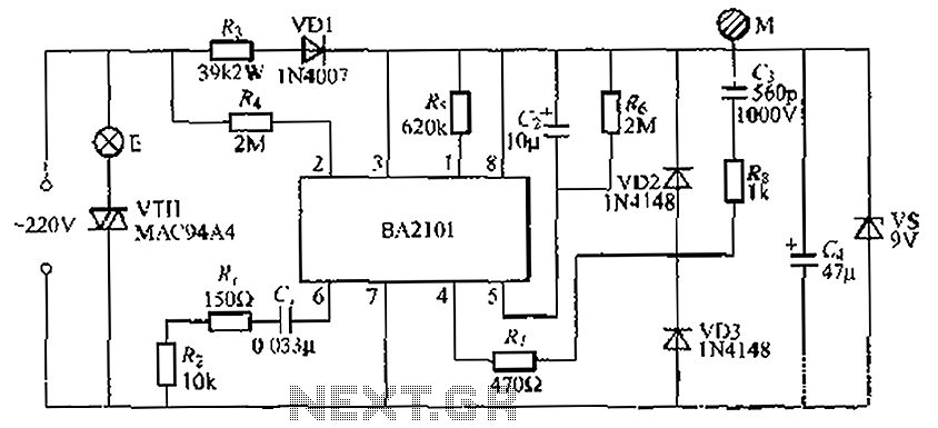
The BA2101 is a dimming controller utilizing an ASIC to create a barrel of light touch stepping. It is a non-constant lamp suitable for heir light. Each touch on the electrode sheet M can adjust the lamp brightness through...

The circuit produces a pleasing and accurate imitation of sound, making it suitable for sound effects such as doorbells. It generates a two-tone effect that closely resembles the sound of a cuckoo. This circuit is designed to create a two-tone...
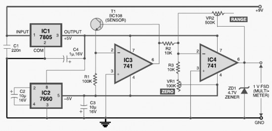
This DIY digital thermometer circuit can measure temperatures up to 150°C with an accuracy of ±1°C. The temperature is displayed on a 1V full scale deflection. The digital thermometer circuit is designed to provide accurate temperature readings within a specified...
The core of the circuit is a two-transistor flasher with frequency modulation applied to the base of the first transistor. When the pushbutton is pressed, the oscillation frequency increases to a peak, and upon release, the frequency decreases due...
This is the basis of electronics telephone sets. You can use it to replace the talking circuit of an old telephone set with new design, better noise rejection and reliability one. Also you can use it to build a...
Warning: include(partials/cookie-banner.php): Failed to open stream: Permission denied in /var/www/html/nextgr/view-circuit.php on line 713
Warning: include(): Failed opening 'partials/cookie-banner.php' for inclusion (include_path='.:/usr/share/php') in /var/www/html/nextgr/view-circuit.php on line 713