
Micro ampere meter circuit using uA 741

The micro ampere meter circuit employs the 741 operational amplifier, which is known for its versatility and stability in low-voltage applications. The circuit is designed to amplify the small voltage drop generated across the known resistor R when a microampere level current flows through it. The choice of a non-inverting amplifier configuration ensures that the output voltage is in phase with the input voltage, providing a straightforward and linear relationship between the input current and the output voltage.
The circuit's operation begins with the input current flowing through the resistor R, creating a voltage drop (V_R) according to Ohm's Law (V = I * R). This voltage drop is then fed into the non-inverting terminal of the op-amp. The op-amp amplifies this voltage drop, and the gain can be adjusted by selecting appropriate feedback and input resistors, providing flexibility in scaling the output to match the desired full-scale deflection of the meter.
The output of the op-amp drives a display mechanism, which could be an analog meter or a digital readout, depending on the design requirements. The calibration of the meter is crucial; it must be performed by adjusting the known resistance R or the feedback components of the op-amp to ensure accurate readings across the expected range of input currents.
Overall, this micro ampere meter circuit is an effective tool for measuring very low currents with precision, leveraging the amplification capabilities of the 741 op-amp to provide clear and readable output indicative of the input current levels.The micro ampere meter shown here is basically a DC millivolt meter. The circuit gives full scale deflection for 0. 1V input. The current to be measured is passed through a known resistance R and the voltage drop across it is measured. Here the IC 1 uA 741 op-amp is wired as a non inverting amplifier. 🔗 External reference
Related Circuits
The circuit depicted in the figure utilizes a thermal protection system featuring the MIC2951 component. The temperature threshold can be adjusted by modifying resistor R2. The thermal protection circuit employing the MIC2951 is designed to monitor and regulate temperature within...
This wireless FM microphone is easy to construct and offers a useful transmitting range of over 300 meters in open air. Despite its minimal component count and a 3V operating voltage, it can effectively penetrate three floors of an...
This project was designed and constructed as enhancement to the 0-30V Stabilized Power Supply Project with the DIY electronics hobbyist in mind. The circuit uses a single PIC Microchip to perform the Voltage, Current and Temperature conversions and display...
The lantern control circuit allows for the management of 30 outputs through an external driver circuit, specifically designed for water sports or large decorative lantern applications. The circuit features a control pulse generator, which regulates the lights, and an...
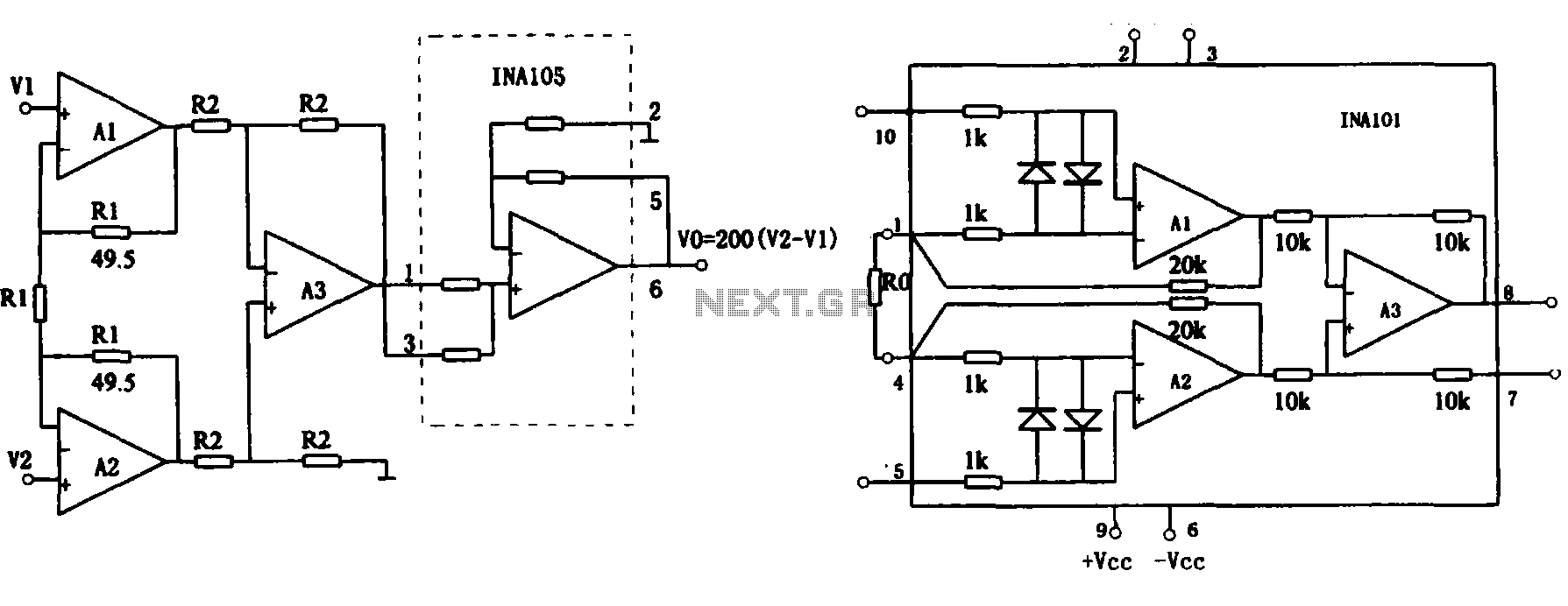
This document describes the extended common mode input voltage range of an instrument amplifier circuit. The circuit consists of three precision instrument amplifiers, A1, A2, and A3, which can be INA101 or INA102 models. The figure illustrates that A1,...

An NPN bipolar transistor is typically utilized for relay switching, particularly with 12V coil-rated relays, as it helps maintain circuit separation. A diode is also added to prevent issues. The necessity of driving the relay with a transistor depends...