
Fun Game Circuits

1. Player X starts by momentarily pressing reset switch S1, followed by pressing and releasing either switch S2 or S3. They then press switch S4 to read the score displayed (noted as X1).
2. Player Y follows the same procedure: pressing switch S1, then S2 or S3, and finally switch S4 to note their score (Y1).
3. Player X repeats the steps from the first round to note their new score (X2), adding it to their previous total. Player Y does the same during their turn.
4. The game continues until one player reaches or exceeds a total of 100 points, thereby winning. Multiple players can participate, each taking turns to score. The assembly can be performed on a multipurpose board, with the display (LEDs and 7-segment display) mounted on top of the cabinet alongside the three switches. The circuit operates at a supply voltage of 5V.
The circuit design incorporates a timer IC to manage timing functions, ensuring that the game runs smoothly and that the scoring is accurately tracked. The two decade counters are essential for counting up and down, allowing players to increment or decrement their scores based on the switch pressed. The BCD outputs from the counters provide a digital representation of the score, which is then processed by the BCD to 7-segment decoder/driver IC3. This IC converts the binary-coded decimal output into a format suitable for the 7-segment display, enabling clear visual feedback of the scores.
Switch S1 serves a critical role in resetting the game state, ensuring that each round starts from a clean slate. The use of momentary switches S2 and S3 allows players to interact with the scoring system in real-time, with the rapid changes in the counter outputs providing an engaging and dynamic gameplay experience. The latching function of the output from IC2 ensures that players can accurately read and record their scores after each turn.
The common-anode display (DIS1) is designed to show the current score, and its operation is contingent upon pressing switch S4, which allows players to view the score at their convenience. This design consideration enhances user interaction, as players can choose when to check their scores without disrupting the flow of the game.
The overall assembly of the circuit on a multipurpose board facilitates easy construction and customization. Positioning the display and switches on the cabinet ensures that players can easily access controls and view scores during gameplay. The choice of a 5V supply voltage allows for compatibility with standard electronic components, making this circuit both practical and efficient for recreational use.Play this game alone or with your friends. The circuit comprises a timer IC, two decade counters and a display driver along with a 7-segment display. The game is simple. As stated above, it is a scoring game and the competitor who scores 100 points rapidly (in short steps) is the winner.
For scoring, one has the option of pressing either s witch S2 or S3. Switch S2, when pressed, makes the counter count in the forward direction, while switch S3 helps to count downwards. Before starting a fresh game, and for that matter even a fresh move, you must press switch S1 to reset the circuit.
Thereafter, press any of the two switches, i. e. S2 or S3. On pressing switch S2 or S3, the counter`s BCD outputs change very rapidly and when you release the switch, the last number remains latched at the output of IC2. The latched BCD number is input to BCD to 7-segment decoder/driver IC3 which drives a common-anode display DIS1.
However, you can read this number only when you press switch S4. The sequence of operations for playing the game between, say two players X` and Y`, is summarised below:1. Player X` starts by momentary pressing of reset switch S1 followed by pressing and releasing of either switch S2 or S3.
Thereafter he presses switch S4 to read the display (score) and notes down this number (say X1) manually. 2. Player Y` also starts by momentary pressing of switch S1 followed by pressing of switch S2 or S3 and then notes down his score (say Y1), after pressing switch S4, exactly in the same fashion as done by the first player.
3. Player X` again presses switch S1 and repeats the steps shown in step 1 above and notes down his new score (say, X2). He adds up this score to his previous score. The same procedure is repeated by player Y` in his turn. 4. The game carries on until the score attained by one of the two players totals up to or exceeds 100, to be declared as the winner.
Several players can participate in this game, with each getting a chance to score during his own turn. The assembly can be done using a multipurpose board. Fix the display (LEDs and 7-segment display) on top of the cabinet along with the three switches. The supply voltage for the circuit is 5V 🔗 External reference
Related Circuits
Significant overengineering was necessary to replicate a previous capacitive scanner. At the local hackerspace OSAA, a brainstorming session was initiated with Pedersen, AsbjG rn, and Flemming, who quickly generated numerous creative ideas. The discussion took an interesting turn when...
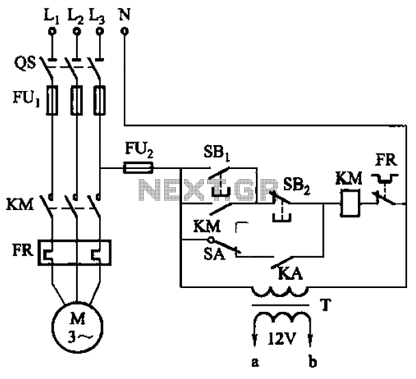
The circuit illustrated in Figure 3-81 employs a transistor delay circuit to facilitate start-stop cycle control. It can operate in both manual and automatic modes. The circuit is primarily governed by the motor run time circuit, which includes transistors...
This discussion covers three different Xenon flashing circuits from disposable cameras. From these circuits, unique techniques not found in any theoretical literature will be presented. The first circuit consists of six building blocks. An old disposable flash camera and...
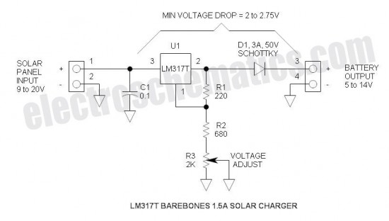
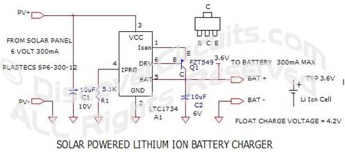
This is a simple and cost-effective solar battery charger that can be constructed by hobbyists. It has some limitations compared to other similar controllers, but it also provides several benefits. While primarily designed for charging lead-acid batteries, it can...
The controller for the Hybrid Power Plant (HPP) is represented in a block diagram format. It consists of 440 Wp photovoltaic modules, a 1 kW wind turbine, and a 5 kW diesel engine as a backup power source. The...
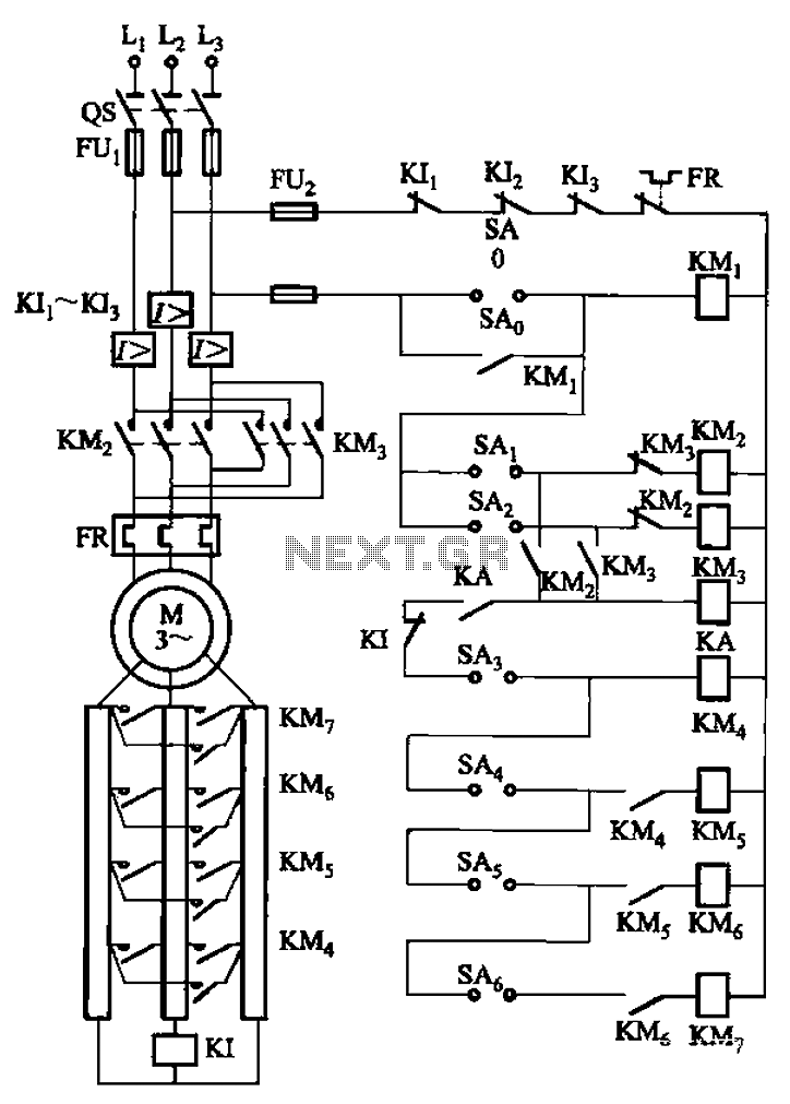
The circuit depicted in Figure 3-168 utilizes a controller for speed grading and reversing control. A reverse brake is connected to the rotor circuit through an overcurrent relay, labeled KI, for control. The current relay KIi to KI3 serves...