
Multifunction Passive 7400 RFID Tag
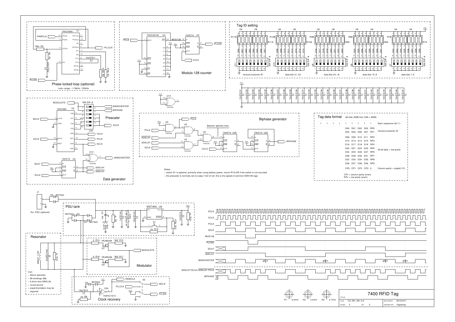
Typically, an EM4100 transponder operates at 125 kHz using amplitude modulation (ASK). The most prevalent encoding method is Manchester encoding at a baud rate of 2 kbps. The transponder transmits 64 bits of data, including a 32-bit unique ID, an 8-bit version or manufacturer number, a 9-bit header, a 14-bit checksum, and a 1-bit trailer. The data stream includes a unique synchronization pattern, consisting of nine consecutive '1' bits at the beginning. A key characteristic of the transponder is its ability to derive power from the electromagnetic field generated by the RFID reader. Achieving a 7400-based tag powered entirely by the EM field represents a significant goal.
Measurements were conducted on available RFID readers at the hackerspace using a basic setup. A coil was tuned to resonate with a parallel capacitor at 125 kHz to assess the power extraction capability. A bridge rectifier using Schottky diodes was connected to the resonant tank (approximately 3.3 mH with 470 pF) and terminated with a 10 µF capacitor, with resistors of 4.7 kΩ, 12 kΩ, and 47 kΩ used for load testing. The results indicated that maximum power transfer occurred at a current load of approximately 700 µA, yielding a voltage of around 19 V through quadratic interpolation of the measurements. This translates to over 13 mW of power extractable from the EM field. The maximum current while maintaining the capacitor above 3.3 V was approximately 2 mA, which is sufficient to power various 74HCxx circuits.
The chosen logic family for this application is the 74xx series, specifically the HC variants. These chips utilize CMOS technology, resulting in minimal static current draw (quiescent current). Power dissipation occurs primarily during input and output transitions, as specified in the datasheet's power dissipation capacitance. Assuming operating conditions of 3.3 V, 700 µA, and 125 kHz, the resonant tank can support chips with a total capacitance of 1700 pF (U*C=I*t). This indicates adequate power availability for numerous chips and I/O pins. Using higher frequency tags, such as those operating at 13.56 MHz, presents challenges due to significantly increased power consumption, making them impractical for this design.
Regarding the HCT family of chips, they are unsuitable for this application due to their higher average quiescent current and additional current draw at each input, which is a result of TTL level compatibility specifications. The input stage of an HCT gate introduces further complications that are not conducive to the low-power design goals of this RFID tag project.Some serious overengineering was required to match my previous capacitive scanner. At the local hackerspace OSAA I went on to start a brainstorm with pedersen, AsbjG rn and Flemming, who promptly came up with a lot of funnyideas. All nice and well until Flemming mentioned RFID (he is the creator of the hackerspace`s access system, HAL900, which is based on RFID).
Now that is a thought. Of course, the first thoughts were with an RFID reader, but there have been made many of them already and that would be boring. However, the idea materialized to make an RFID Tag. I don`t know who mentioned it first and, as with brainstorms, the ideas materialize as part of the joining of minds.
The idea was born, make a tag based entirely on 7400 logic. An RFID tag, sends a (unique) code modulated on a carrier wave. Most tags are passive, which means that there are no batteries and the tag only sends some ID data. Common tags use the EM4100 protocol. Many EM4100 compatible use the same internal transponder chip and are available in several configurations which differ in encoding protocol and baud rate. A general tag`s transponder has the following features: The EM4100 transponder uses 125kHz and AM modulation ( ASK ).
They are available in all kinds of encoding, but the Manchester encoding type with a 2kbs baud rate is most common. The EM4100 transponder sends 64 bits of data which encapsulate a 32 bit unique ID, an 8 bit version/manufacturer number, 9 bits header, 14 bits interspersed checksum (parity) and a 1 bit trailer.
The data from the tag is encoded such that a unique pattern is embedded for synchronization to the data stream. EM4100 transponders send nine bits of `1` in sequence which cannot occur anywhere else than at the start of the data stream.
The main feature of a transponder is that it derives power from the EM field transmitted by the RFID reader. That would be a great feature to achieve, powering a 7400 based tag entirely on the EM field. A measurement was performed on the RFID readers that were available at the hackerspace using a simple setup.
Take a coil, match it at resonant frequency with a parallel capacitor to 125kHz and see how much power can be drained. A bridge rectifier (with Schottky diodes) connected to the resonant tank (~3. 3mH with 470pF), terminated with a 10 µF capacitor, was drained by a resistor at 4k7, 12k and 47k. It turns out that the maximum power transfer occurs at a current load of about 700 µA, where the voltage reaches about 19V (a simple quadratic interpolation of the measurement).
With other words, more than 13mW of power can be drained from the EM field. The maximum current, while keeping the capacitor over 3. 3V was about 2mA. This should be enough to power a lot of 74HCxx circuits. The 74xx family to use here is HC. These chips are entirely CMOS and have almost no static current draw (the quiescent current). They only dissipate on transitions of the inputs and outputs, which is specified in the datasheet as the power dissipation capacitance. Assuming 3. 3V, 700 µA and 125kHz, then the resonant tank can power chips with a total capacitance of 1700pF (U*C=I*t).
This means there should be enough power to cope with a lot of chips and I/O pins. Using a higher frequency tag, like the 13. 56MHz types, is much more problematic. The two orders of magnitude in frequency translate directly into two order of magnitude higher power consumption. And, since power is not a commodity in this design, it is pragmatically not possible to use the high frequency tags.
A note on the HCT family: these chips cannot be used in this design. The HCT family has an average higher quiescent current and, more importantly, an additional current draw at each input due to the TTL level compatibility specification. The input stage of an HCT gat 🔗 External reference
Related Circuits
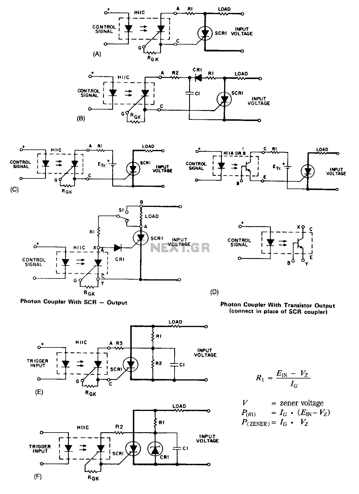
A basic circuit to trigger a silicon-controlled rectifier (SCR) is illustrated in Figure 67-1A. This circuit has the limitation that the blocking voltage of the photonic coupler output device dictates the circuit's blocking voltage, despite the SCR's higher voltage...
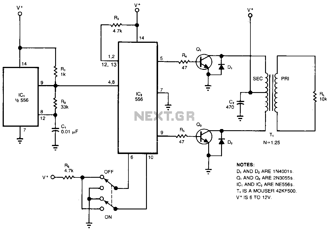
The circuit converts a DC voltage (V+) into a high-amplitude square wave within the audio frequency range. The dual timer, IC2, serves as a cost-effective alternative to traditional transformers for providing complementary base drive to the power transistors, Q1...
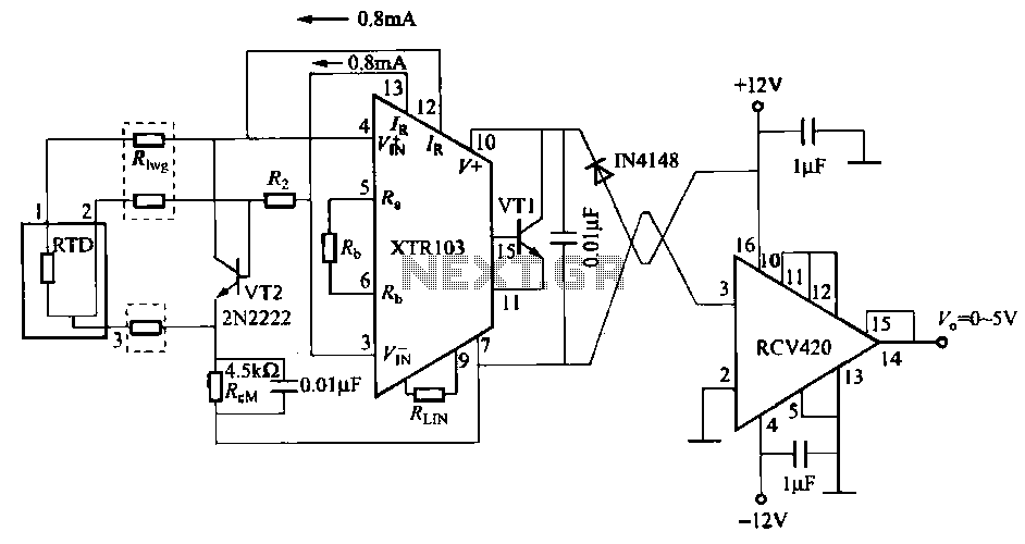
When the RTD temperature sensor is positioned far from the amplifier, the resistance of the sensor leads and their susceptibility to interference and other issues cannot be overlooked. The circuit shown in the figure addresses this problem. It utilizes...
The goal is to control the speed of a 6-volt brush DC motor using a linear potentiometer and to create an oscillating speed effect, with the oscillation frequency also adjustable via a linear potentiometer. The desired complete cycle peak-to-peak...
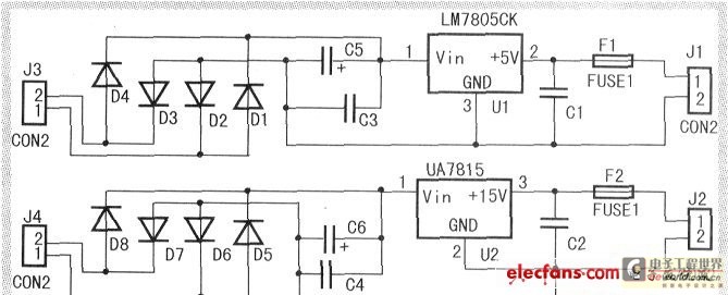
When the input voltage is between 198-242V, the average load current should be maintained at 0.5-1A, and the output voltage must remain at 15V with an error margin of less than 5%. The design and measurement of the stabilized...
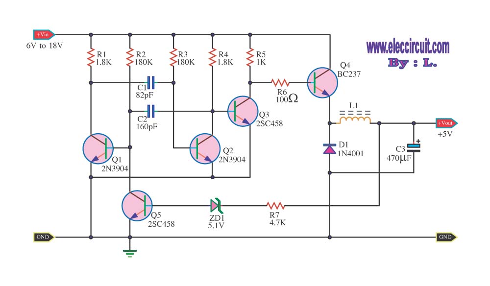
The circuit reduces voltage size or functions as a step-down voltage converter circuit, which is a DC regulated circuit model utilizing a switching converter. This design generates a specific voltage output. The step-down voltage converter, also known as a buck...