
Functional Block Diagram for AD524 pin and internal circuit

The AD524 low-drift instrumentation amplifier is designed for high-precision applications requiring minimal drift and noise characteristics. With a drift voltage of just 0.5 mV, this amplifier maintains stability in various operating conditions, making it ideal for sensitive measurements. The low noise level of 0.3 mVp-p ensures that the signal integrity is preserved across a wide frequency range, particularly in low-frequency applications where noise can significantly impact performance.
The amplifier's linearity is critical for applications that demand accurate signal reproduction. With a linearity specification of 0.0030 at a gain of 1, users can expect reliable performance across different gain settings. The high CMRR of 120 dB further enhances the amplifier's ability to reject common-mode signals, which is essential in environments with significant electrical noise.
The adjustable gain feature allows users to configure the amplifier for a variety of applications, ranging from low-gain settings of 1 to high-gain settings of 1000. This versatility is complemented by the amplifier's gain bandwidth of 25 MHz, ensuring that it can handle fast signal changes without distortion. The output slew rate of 5 V/ms indicates that the amplifier can respond quickly to input signal variations, making it suitable for dynamic measurement scenarios.
The internal architecture of the AD524 includes essential protective features that safeguard the input and output stages, ensuring long-term reliability. The pre-release stage processes the incoming signal before amplification, which helps to minimize distortion and improve overall performance. The differential instrumentation amplifier configuration allows for precise amplification of small signals in the presence of noise.
In terms of power supply requirements, the AD524 operates within a range of 6 to 18 V, making it compatible with various power supply designs. This flexibility allows for easy integration into existing systems without the need for extensive modifications.
Overall, the AD524 low-drift instrumentation amplifier is a robust solution for applications requiring high precision, low noise, and adjustable gain settings, making it a valuable component in the field of electronic instrumentation.AD524 low-drift (drift voltage 0.5mV, maximum drift 25 mV door C), low noise (0.3mVp p, 0.1-10Hz), good linearity ( 0.0030/0, a gain of l), high CMRR (120dB) gain bandwidth of 25MHz, stepper adjustable gain (gain 1,10,100,1000), output slew rate of 5V/ms precision instruments put amplifier. Power supply range is (6 ~ 18V). The pin and internal circuit functional block diagram in Fig. 10 - 10. AD524 internally by input protection, output amplification recognize the difference between sub-gain instrumentation amplifier and setting circuit, and the like.
Signal after, pin input is first pre-release, and then by the differential instrument is an amplified output from a feet., ?, ? feet respectively connection feet, accurately set the internal amplifier gain set to 10, 100, when not connected to a gain of foot 1.
In addition, these pins or re-train people in resistance when, ? pin feedback input resistor is connected, can be adjusted gain of the amplifier. Therefore, AD524 is a gain adjustment of non- regular convenient instrumentation amplifier.
Related Circuits
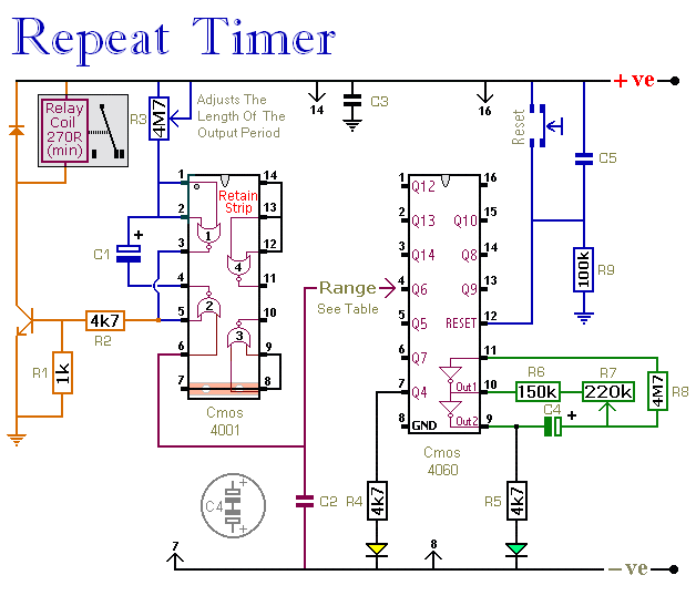
The CMOS 4060 integrated circuit (IC) features two built-in inverters located at pins 9, 10, and 11, which must be interconnected to create an oscillator. The output of this oscillator is available at Pin 9, which continuously alternates between...

This is a design for a scoring game circuit suitable for any occasion where dice are used. The circuit utilizes a NE555 timer, a 74LS192 counter, a 74LS247 decoder, and a seven-segment LED display. The timer IC1 generates a...
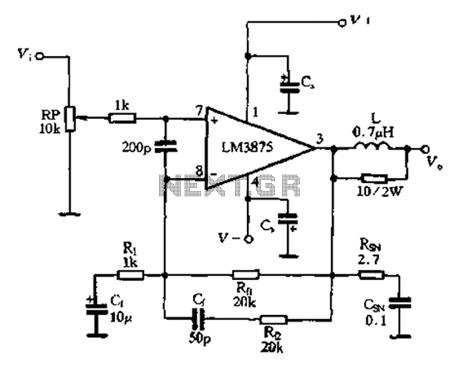
The 875T and LM3876T are high-performance 40W power amplifier integrated circuits (ICs). They operate within a frequency range of 20Hz to 20kHz with a continuous average power output under an 8-ohm load and exhibit a distortion level of only...
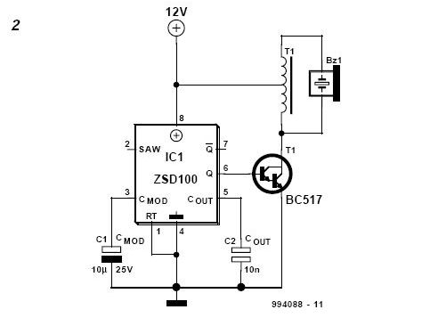
The DIY Electronic Siren circuit described here can produce three distinct US-style siren sounds: DIY police, DIY ambulance, and fire engine. The desired sound can be selected using switch S1. This circuit is suitable for use in toys (such...
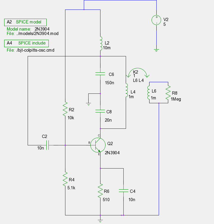
The previous tutorials on SPICE simulation in Fedora Electronic Lab have introduced various concepts. This post focuses on Part 3, assuming familiarity with gschem and completion of a course on analog electronic circuits. It is advised to review the...
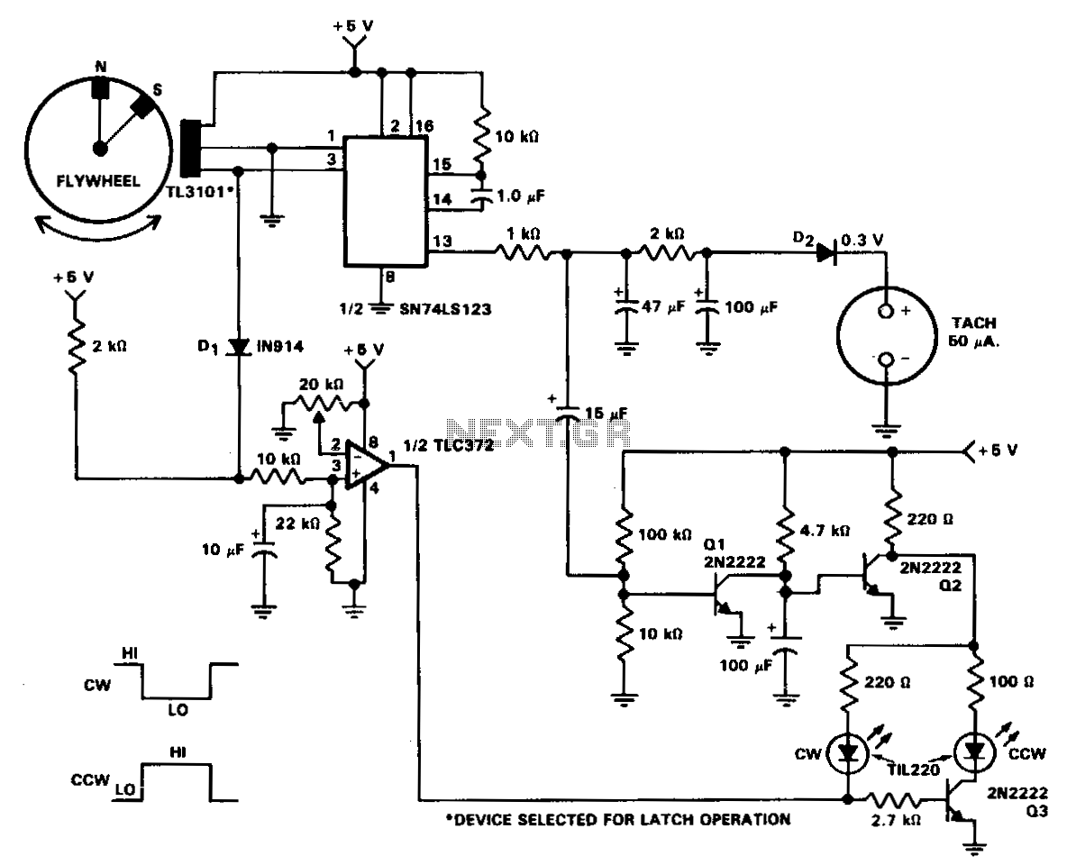
In machine and equipment design, certain applications necessitate the measurement of both shaft speed and direction of rotation. The circuit of a tachometer, which also indicates the direction of rotation, is illustrated. A flywheel is equipped with two magnets...