
Scoring Game Circuit

The scoring game circuit serves as an educational tool for understanding basic digital electronics concepts, particularly in the use of timers and counters. The NE555 timer operates in astable mode, providing a continuous clock signal to the 74LS192 counter, which can count both up and down based on the switch inputs. The design incorporates debouncing techniques to ensure that switch presses are registered accurately without multiple counts from a single press.
The 74LS192 counter is a synchronous binary counter that provides a count output in binary format. This output is fed into the 74LS247 BCD to 7-segment decoder/driver, which converts the binary count into a format suitable for display on the seven-segment LED. This allows for clear and immediate visual feedback of the current score.
Power management is crucial in this design, with the option for a 9V battery or regulated power supply ensuring reliable operation. The choice of components allows for a compact design, suitable for portable applications. The circuit's simplicity and adherence to fundamental electronic principles make it an excellent project for beginners, providing hands-on experience with digital logic and component integration. Each interaction with the circuit reinforces learning about how timers and counters function in a practical context, making it an ideal educational tool.This is a design circuit for scoring game circuit that can be used for all occasions when a dice is needed. The circuit is based on a NE555 timer, a 74LS192 counter, a74LS247 decoder and a & segment LED display.
The timer IC1 will produce the clock for the counter IC(IC2) whose frequency is determined by R1 and C2. When S2 is pressed the IC2 will co unt in up mode and when S3 is pressed the IC2 will count in down mode. This is the figure of the circuit; The IC 3 will decode the count to display it on the seven segment LED display. That is about the working of the circuit. The circuit is designed strictly sticking on to the basics of counters and is a good one for beginners.
There is nothing big deal. To play the game switch the power ON and press S1 to reset the counter. Now press S2 or S3 and release. The IC2 will hold the last count. Now press S4 to see the score on display. That`s your score. Now the second person can try. Each time one tries, he should press the S1 to reset the count and then press S2 or S3 and then S4 to see the score. Circuit can be powered from a 9V radio cell or a 9V regulated DC power supply. 🔗 External reference
Related Circuits
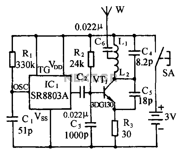
The circuit consists of a language and sound FM transmitter. It is mounted on a 25mm x 35mm PCB, designed to be placed on a table. When activated by pressing the micro switch SA, the circuit transmits an FM...
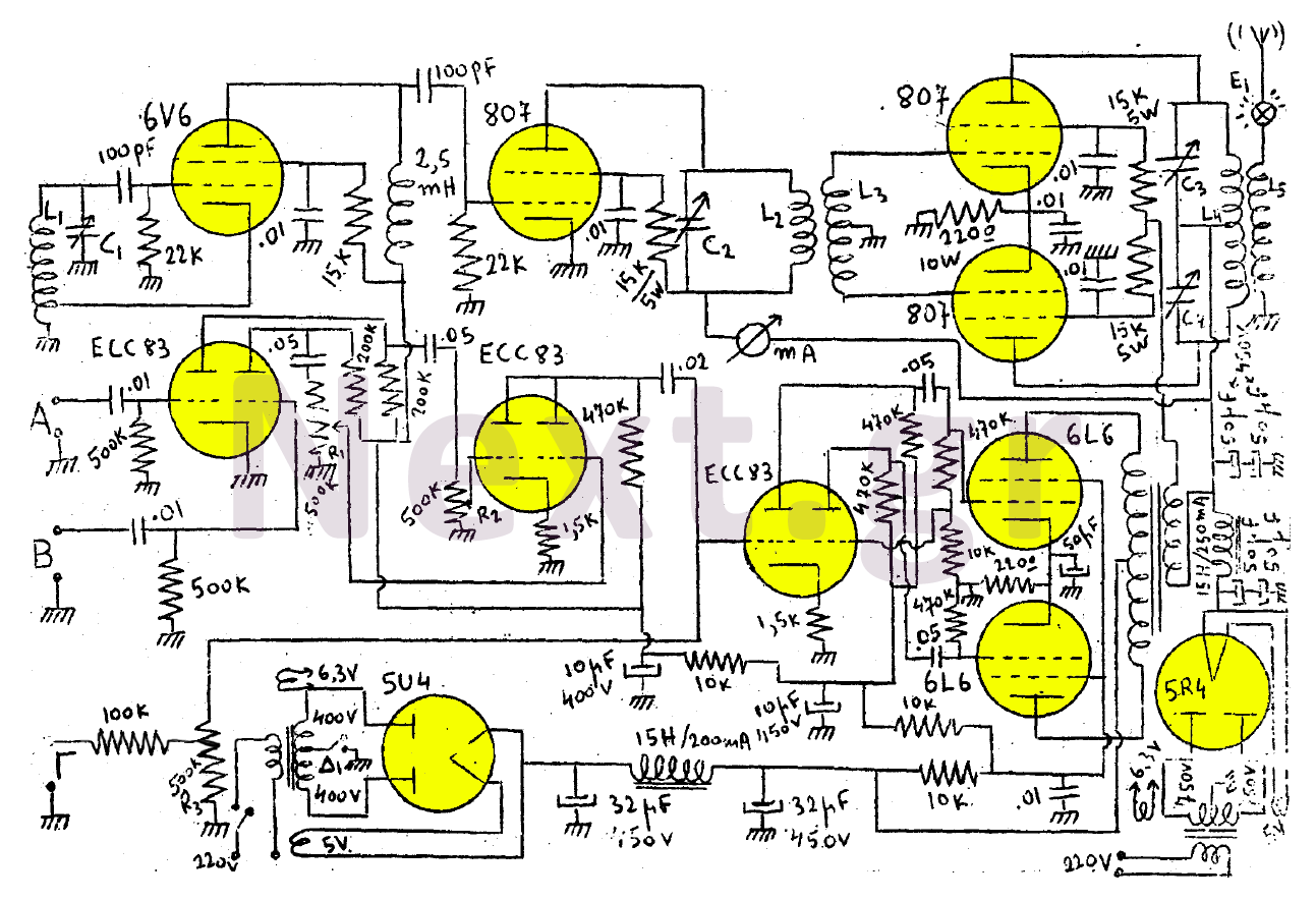
This transmitter consists of a 6V6 oscillator that excites an 807 buffer. The final stage includes two 807 tubes arranged in a Push-Pull configuration. The amplifier is built with three series-connected double-triodes (ECC83) and concludes with two 6L6 tubes...
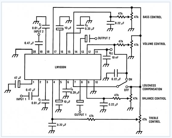
The LM1036 is a DC-controlled tone (bass/treble), volume, and balance circuit designed for stereo applications in car radios, televisions, and audio systems. It features an additional control input that facilitates loudness compensation. Four control inputs enable the adjustment of...
If the transmitter stick-potentiometer delivers a voltage about 2 - 3 V, this circuit will be suitable. If you want to avoid using the battery cable (supplying Vcc for IC1 and -2), you can use a separate 5V supply...
In the event of a sudden power failure in an elevator, it is crucial for the duty officer in the distribution room to be alerted promptly to prevent panic among passengers trapped inside. The following describes a sound alarm...
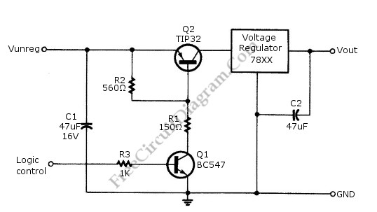
Logic power control of an analog regulator can be useful in applications where a digital circuit or controller needs to manage a power source, such as in EEPROM programmers or other power control systems. This circuit provides ON-OFF control...
Warning: include(partials/cookie-banner.php): Failed to open stream: Permission denied in /var/www/html/nextgr/view-circuit.php on line 713
Warning: include(): Failed opening 'partials/cookie-banner.php' for inclusion (include_path='.:/usr/share/php') in /var/www/html/nextgr/view-circuit.php on line 713