
Fundamentals of Electrical Engineering and Monostable Multivibrator

The 555 timer IC is a versatile component widely used in various timing applications. In this monostable configuration, the circuit is designed to produce a single output pulse of a defined duration in response to a trigger input. The timing period is primarily determined by the resistor (Rt) and capacitor (Ct) values connected to the 555 timer. The relationship between these components is governed by the formula T = 1.1 * Rt * Ct, where T is the timing interval in seconds.
In practical applications, the circuit can be used in various scenarios, including generating time delays, pulse-width modulation, or as a simple timer for applications such as automatic lights or sound effects in toys. The choice of components significantly influences the performance and stability of the circuit. For instance, using high-quality capacitors with low leakage and precision resistors can enhance timing accuracy, which is crucial in applications where timing is critical.
In addition, the design incorporates a signal conditioning stage with R3 and C1 to ensure that the input signal is clean and free of noise that could cause false triggering. This is particularly important in environments with electrical interference, which could otherwise lead to erratic behavior of the circuit.
The 555 timer's ability to operate across a wide voltage range allows for flexibility in power supply choices, making it suitable for battery-operated devices as well as those powered by standard AC adapters. The inclusion of C2, although not essential, provides an additional layer of noise filtering, which can be beneficial in sensitive applications.
Overall, the 555 timer in this monostable configuration exemplifies a fundamental yet powerful electronic circuit, demonstrating the principles of timing and signal conditioning, and serves as an excellent introduction to timer circuits for both educational and practical purposes.This is one of the most basic 555 circuits. This circuit is part of this chips datasheet, complete with the math needed to design to specification, and is one of the reasons a 555 is referred to as a timer. The green LED shown on the illustration lights when the 555 output is high (i. e. , switched to Vcc), and the red LED lights when the 555 output is low (switched to ground). This particular monostable multivibrator (also known as a monostable or timer) is not a retriggerable type. This means once triggered it will ignore further inputs during a timing cycle, with one exception, which will be discussed in the next paragraph.
The timer starts when the input goes low, or switched to the ground level, and the output goes high. You can prove this by connecting the red wire shown on the illustration between ground and point B, disconnecting it, and reconnecting it. It is an illegal condition for the input to stay low for this design past timeout. For this reason R3 and C1 were added to create a signal conditioner, which will allow edge only triggering and prevent the illegal input.
You can prove this by connecting the red wire between ground and point A. The timer will start when the wire is inserted into the protoboard between these two points, and ignore further contacts. If you force the timer input to stay low past timeout the output will stay high, even though the timer has finished.
As soon as this ground is removed the timer will go low. Rt and Ct were selected for 3 seconds timing duration. You can verify this with a watch, 3 seconds is long enough that we slow humans can actually measure it. Try swapping Rt and Ct with the 27 KO resistor and the 100 µF capacitor. Since the answer to the formula is the same there should be no difference in how it operates. Next try swapping Rt with the 270 KO resistor, since the RC time constant is now 10 times greater you should get close to 30 seconds.
The resistor and capacitor are probably 5% and 20% tolerance respectively, so the calculated times you measure can vary as much as 25%, though it will usually be much closer. Another nice feature of the 555 is its immunity from the power supply voltage. If you were to swap the 9V battery with a 6V or 12 battery you should get identical results, though the LED light intensity will change.
C2 isn`t actually necessary. The 555 IC has this option in case the timer is being used in an environment where the power supply line is noisy. You can remove it and not notice a difference. The 555 itself is a source of noise, since there is a very brief period of time that the transistors on both sides of the output are both conducting, creating a power surge (measured in nanoseconds) from the power supply.
This transistor is simply a switch that normally conducts until pin 2 (which is connected through the comparator C1, which feeds the internal flip flop) is brought low, allowing the capacitor Ct to start charging. Pin 7 stays off until the voltage on Ct charges to 2/3 of the power supply voltage, where the timer times out and pin 7 transistor turns on again, its normal state in this circuit.
) will show the sequence of switching, with red being the higher voltages and green being ground (0 volts), with the spectrum in between since this is fundamentally an analog circuit. is the starting and ending point for this circuit, where it is waiting for a trigger to start a timing cycle.
At this point the pin 7 transistor is on, keeping the capacitor Ct discharged. shows the circuit in the middle of switching off when it hits timeout. The capacitor has charged to 67%, the upper limit of the 555 circuit, causing its internal flip flop to switch states. As shown, the transistor hasn`t switched yet, which will discharge Ct when it does. 🔗 External reference
Related Circuits
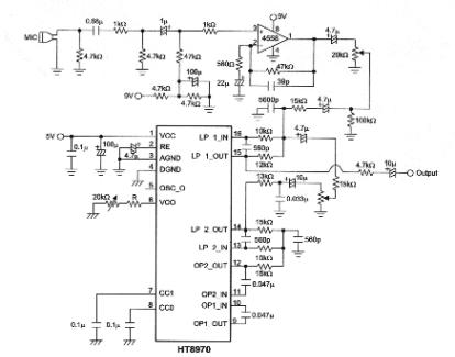
The objective of this project is to develop a multi-effect guitar processor capable of altering the tonal characteristics of a guitar. This device aims to provide a wide range of unique sounds, enhancing the entertainment value for users. The...
In a previous chapter, the use of a transistor as an electronic switch was discussed. This chapter will explore how one transistor can switch another. The diagram illustrates a pair of cross-coupled transistors. The input push buttons of the...
Embedded systems serve as the core of most electronics-based systems, enabling data access, processing, storage, and control. While some simple electronic circuits can be designed without a microprocessor or microcontroller, this approach is often economically impractical, except for basic...
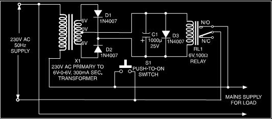
This is a low-cost protection circuit designed to safeguard electrically operated home appliances, such as TVs, DVD players, refrigerators, and other devices, during sudden power outages and the subsequent restoration of mains supply. Appliances like refrigerators and air conditioners...
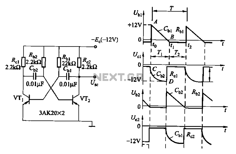
Also known as a no-shot multivibrator, this circuit is often utilized as a pulse (square wave) signal source. The astable flip-flop functions as a strong positive feedback amplifier, with its two branches coupled by an RC timing circuit, resulting...
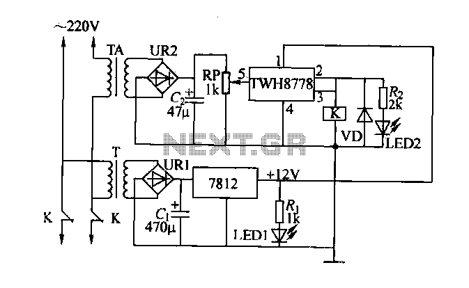
An electric power limiter circuit restricts the user load, ensuring that household appliances operate within a specified normal current range. When the load exceeds a predetermined threshold, the power supply is disconnected. This circuit utilizes the high-power integrated TWH8778...