
RC coupled self-excited multivibrator circuit
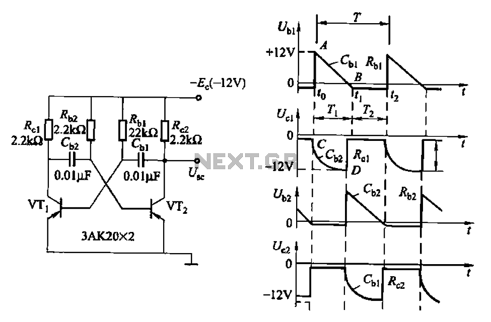
The astable multivibrator is a fundamental electronic circuit that generates a continuous square wave output without requiring any external triggering. It consists of two active devices, typically bipolar junction transistors (BJTs) or operational amplifiers, configured to provide positive feedback. The circuit is characterized by its two timing resistors and capacitors, which determine the frequency and duty cycle of the output waveform.
In a typical astable multivibrator configuration, the two timing components (R1, R2, and C1) are connected in such a way that they charge and discharge alternately, creating a rapid oscillation. The charging and discharging times are governed by the time constants of the RC network, which can be calculated using the formulas:
- Frequency (f) = 1 / (T1 + T2)
- Where T1 = 0.693 * (R1 + R2) * C1 (time high)
- And T2 = 0.693 * R2 * C1 (time low)
This results in a square wave output that can be used in various applications, such as clock pulses for digital circuits, tone generation, and signal modulation. The duty cycle, which is the ratio of the high time to the total period of the waveform, can be adjusted by varying the resistances and capacitance values.
The astable multivibrator is widely used due to its simplicity, low cost, and versatility. It can be implemented using discrete components or integrated circuits, making it suitable for a range of applications in digital electronics, audio signal generation, and timer circuits. Proper design considerations, such as component tolerances and power supply variations, should be taken into account to ensure reliable operation in practical scenarios.Also known as no-shot multivibrator - often used as a pulse (square wave) signal sources. Astable flip-flop is a strong positive feedback amplifier, its two branches are couple d RC timing circuit, so there is no steady state. RC coupled self-excited multivibrator circuit
Related Circuits
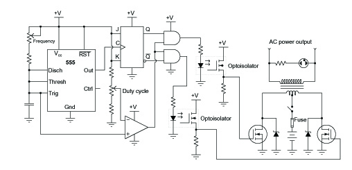
A common topology for DC-AC power converter circuits employs a pair of transistors to switch DC current through the center-tapped winding of a step-up transformer. Examine the check plot images from a PCB drafting program for a control board...
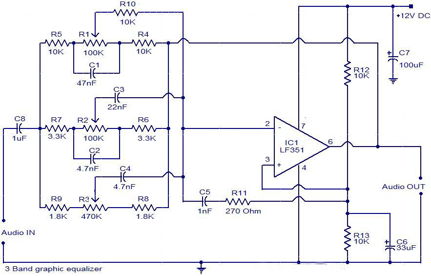
The circuit is a diagram of a simple three-band graphic equalizer circuit. An IC known as the LF351 is utilized in this design. The three-band graphic equalizer circuit is designed to adjust the amplitude of audio signals across three distinct...
This is a solar tracking circuit designed to harness power from sunlight. The circuit operates optimally by maximizing sunlight exposure to generate electricity. The solar tracking circuit utilizes a combination of photovoltaic (PV) cells, sensors, and a microcontroller to adjust...

This circuit operates effectively across a broad frequency spectrum. XTAL 1 serves as a fundamental-frequency crystal. Tl and CI are adjusted to match the input frequency. This circuit can be utilized as a straightforward shortwave converter for AM radios,...
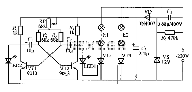
The circuit utilizes a thyristor-controlled unidirectional flashing light string controller. Diodes VT1 and VT2 are connected to a multi-oscillator. Upon powering the circuit, VT1 and VT2 alternately turn on and off. When VT1 is deactivated, VT2 is powered by...

The LTC3113 fixed frequency buck-boost DC-DC converter can be utilized to design various power supply circuits that operate with input voltages that are above, below, or equal to the output voltage. The topology integrated into the IC ensures low...
Warning: include(partials/cookie-banner.php): Failed to open stream: Permission denied in /var/www/html/nextgr/view-circuit.php on line 713
Warning: include(): Failed opening 'partials/cookie-banner.php' for inclusion (include_path='.:/usr/share/php') in /var/www/html/nextgr/view-circuit.php on line 713