
Fuzz box 2
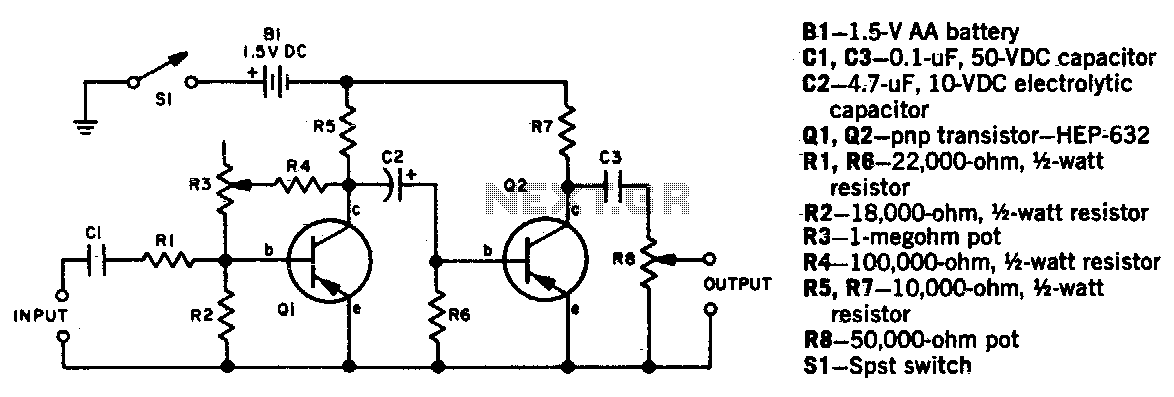
In this circuit, the potentiometer R3 serves as a variable resistor that allows the user to modify the amount of fuzz applied to the audio signal. By rotating R3, the resistance changes, altering the feedback and gain characteristics of the fuzz circuit, which ultimately affects the tonal quality and intensity of the fuzz effect. The second potentiometer, R8, functions as a level control that adjusts the overall output amplitude of the signal coming from the fuzz circuit. This allows the user to balance the fuzz effect with the desired output level, ensuring that the sound remains within a usable range.
To achieve a fuzz-free sound, a bypass switch is integrated into the circuit design. This switch, when engaged, creates a direct path for the audio signal from the input to the output, bypassing the fuzz circuit entirely. This feature is essential for musicians and audio engineers who require a clean sound without any distortion or fuzz artifacts. The bypass switch typically consists of a single-pole double-throw (SPDT) configuration, which allows for seamless switching between the fuzz effect and the clean signal.
In summary, the combination of R3 and R8 allows for versatile sound shaping capabilities, while the inclusion of a bypass switch ensures that users can easily toggle between fuzzed and clean audio outputs, catering to a wide range of musical styles and preferences. The careful selection of component values and configurations will affect the overall performance of the circuit, making it crucial to consider the desired application when designing and implementing this schematic.Potentiometer R3 sets the degree of fuzz, and R8 sets the output level Since the fuzz effect cannot be completely eliminated by R3, fuzz-free sound requires a bypass switch from the input to output terminals. 🔗 External reference
Related Circuits
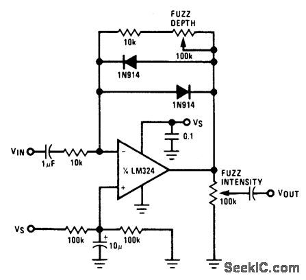
Two diodes in the feedback path of an LM324 operational amplifier create a musical instrument effect known as fuzz by limiting the output voltage swing to ±0.7 V. The resultant square wave primarily contains odd harmonics, resembling the sounds...
The MFOS Noise Toaster circuit comprises seven primary components: a voltage-controlled oscillator (VCO), a white noise generator, a voltage-controlled low-pass filter, a low-frequency oscillator (LFO), a simple attack-release (AR) envelope generator, a simple voltage-controlled amplifier (VCA), and a one-watt...
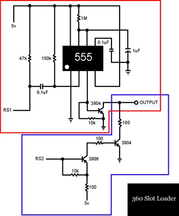
A slot-loading Xbox 360 features a mechanism similar to that of a MacBook, where a CD or DVD is inserted into a thin auto-loading slot rather than using a button to extend a mechanical tray. In contrast, the Xbox...

Various tools can be utilized with a musical instrument to generate different sound effects, with the simplest being the repetition of tone, often referred to as echo. This equipment enhances the music being played. The circuit diagram is designed...
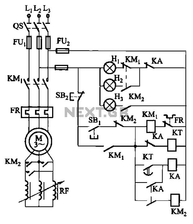
The circuit depicted in Figure 3-165 utilizes a time relay (KT) for controlling the start-up time. Indicator light Hi serves as the power indicator, H2 is designated for the start lights, and H3 functions as the running lights. The circuit...
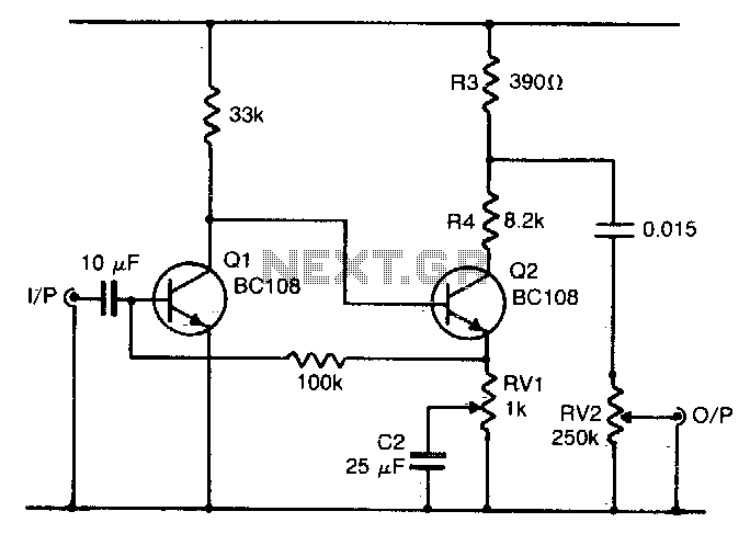
Q1 and Q2 form a voltage amplifier that provides sufficient gain to be overdriven by a relatively low input, such as an electric guitar. The output from Q2 is a squared-off version of the input, resulting in the desired...