
Fuzzbox Using LM741

The circuit described is a specialized audio processing unit designed for electric guitar applications, enabling musicians to achieve a variety of tonal effects through signal manipulation. The use of an operational amplifier (IC1) as the core component allows for precise control over the input signal, ensuring that the guitar's output remains consistent and manageable, even under varying performance conditions.
The emitter follower configuration at the input stage serves to isolate the guitar signal from the amplifier, providing a high input impedance that prevents loading effects that could degrade the guitar's tone. This configuration is critical for maintaining the integrity of the signal, particularly when interfacing with other effects or amplifiers.
The adjustment capabilities provided by potentiometer R9 allow musicians to tailor the gain and restriction applied to the signal, enabling a wide range of sound effects from subtle enhancements to more pronounced alterations. The inclusion of diodes D1 and D2 in an inverse parallel arrangement introduces a clipping mechanism that generates a fuzz effect, characterized by a warm, distorted sound that is highly sought after in various music genres.
At the output stage, the second emitter follower ensures that the signal remains robust and compatible with the amplifier's input, allowing for long cable runs without degradation of the high-frequency response. The adjustment feature on R10 fine-tunes the output level, ensuring that the processed signal meets the requirements of the specific amplifier being used.
The SW1 switch provides a straightforward means of engaging or disengaging the fuzz effect, allowing musicians to switch between clean and processed tones seamlessly during performances. Overall, this circuit is an effective tool for enhancing the sonic capabilities of electric guitars, providing musicians with the flexibility to explore a wide range of tonal possibilities.Many tools can be used with a musical instrument to produce various sound effects and the simplest form is the repetition of tone or a method often called echo . Such equipment to create one more turn on the music that you hear. Circuit diagram is for electric guitar players, this electrical equipment will be able to restrict the guitar signal a
nd will produce a peak wave-cut of the famous peak contains a large number of harmonics. Thus this electric guitar sound will produce a much more rich in tone. Circuit diagram of the input section is equipped with an emitter follower acting as a buffer between the guitar amplifier output limiting, and also can provide a high input impedance. The following is a schematic drawing: IC1 which is an operational amplifier is used to limit the input signal.
The amount of reinforcement of the amplifier and the degree of restriction applied can be adjusted with the potentiometer R9. When the diodes D1 and D2 are connected in inverse parallel lead in a state, it will produce fuzz effect.
At the level of output was still there an emitter follower is to bait the defective guitar signal to the amplifier output power at low impedance. So the cable capacitance and the use of cables that are too long, though no effect on high frequency response.
With the R10 reset output signal from limiting amplifier can be adjusted to fit the guitar amplifier is used. SW1 is a switch to turn on or turn off fuzzbox. 🔗 External reference
Related Circuits
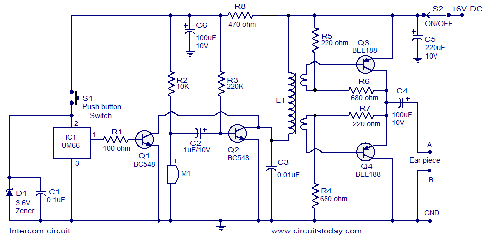
A straightforward intercom circuit designed using transistors. It does not require a changeover switch and can be used similarly to a telephone. This intercom circuit utilizes transistors to facilitate communication between two or more stations without the need for complex...
The circuit presented utilizes modulated rectangular waves of varying time periods to generate ringing tones akin to those produced by a telephone. It requires four astable multivibrators for operation, implemented using two 556 integrated circuits (ICs). The 556 IC...
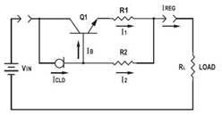
This application datasheet article includes sections that discuss the practical current booster circuit technique, which involves a conventional circuit using a Constant Current Load (CLD) and a current boosting circuit technique. It covers the analysis of the booster circuit...

This circuit illustrates an adjustable regulator configuration that incorporates a voltage regulator. In this design, the LM117 regulator is utilized instead of the LM113 diode for reference. Both regulators necessitate a negative supply to function correctly with respect to...

This application note discusses the use of SEPIC power modules to supply the necessary power for driving high-brightness LED arrays. These arrays serve as display backlights and necessitate a wide dimming range. The SEPIC configuration offers an efficient and...
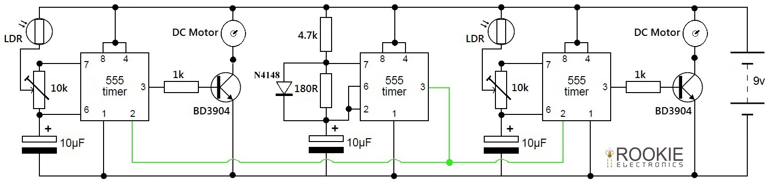
This is a simple and cost-effective approach to a line-following robot. It does not utilize any microcontroller but instead relies on a basic circuit composed of three 555 timers. The robot demonstrates good efficiency in following various curves and...
Warning: include(partials/cookie-banner.php): Failed to open stream: Permission denied in /var/www/html/nextgr/view-circuit.php on line 713
Warning: include(): Failed opening 'partials/cookie-banner.php' for inclusion (include_path='.:/usr/share/php') in /var/www/html/nextgr/view-circuit.php on line 713