
GaAsFET amplifier circuit
The circuit described is a sophisticated control mechanism that utilizes an LM123 voltage regulator to maintain stable output voltage levels while interfacing with a DC-DC converter. The integration of the LM123 allows for efficient voltage regulation, ensuring that the power supply remains consistent even under varying load conditions. The choice of a GaAsFET power relay enhances the performance of the power amplifier, providing high efficiency and fast switching capabilities.
The N-channel MOSFET serves as a critical component in the control circuit, enabling precise control over the base of the 2N6107 pass transistor. By pulling the base to an appropriate level, the MOSFET ensures that the transistor operates in the saturation region, allowing for maximum current flow and minimal heat dissipation. This configuration is essential for maintaining the reliability and longevity of the circuit.
Moreover, the circuit's ability to supply Tum leak during negative potential failures on the gate indicates a protective feature that enhances operational safety. This characteristic ensures that the circuit can handle unexpected conditions without compromising overall functionality.
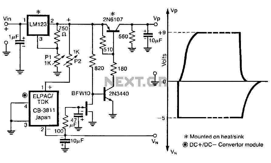
In summary, this control circuit exemplifies a well-designed integration of components that work together to provide efficient power management and reliable operation in electronic applications, particularly in power amplification scenarios.The control circuit operates to double from a positive supply, which, when turned on the power of the first door. and goes off when the first drain as shown in FIG. This circuit integrates the LM123, a three-terminal positive regulator and a dc dc + converter, whose output power drains and gates of GaAsFET-power relay in a power amplifier.
The controller output drives a three-terminal DC + DC converter - which exit through an N-channel lFET properly so as to pull the base of the series pass transistor 2N6107 at a level to turn it on. The circuit will supply Tum leak every time the negative potential on the gate fails. 🔗 External reference
Related Circuits
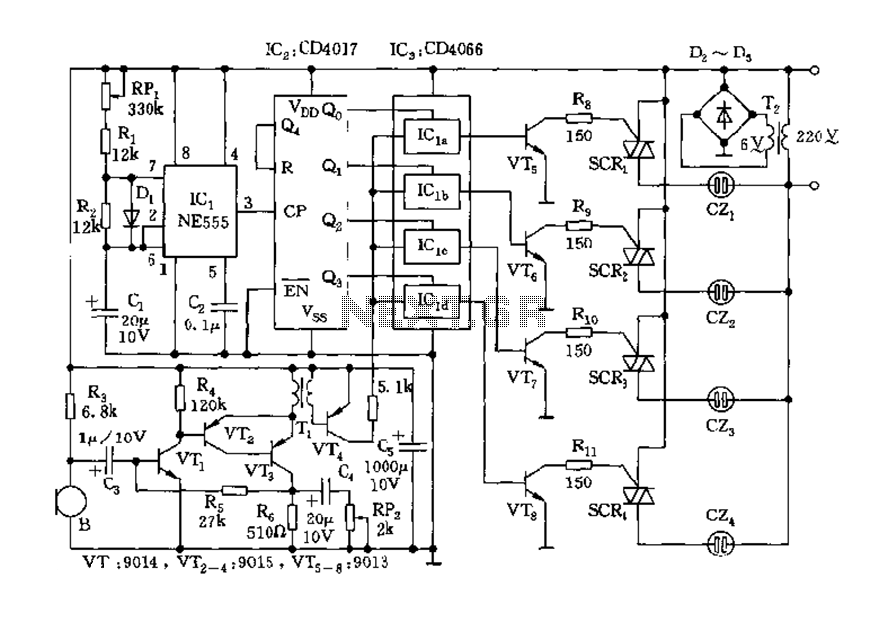
The circuit includes a controller that integrates an acoustic-electric conversion and amplification circuit, a clock pulse generator, a counting circuit, and a control circuit. It manages four accompanying music tracks and flashing lights. Microphones (MIC) convert sound into electrical...
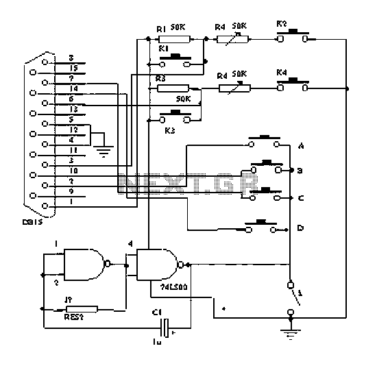
The principle of the dancing blanket is straightforward; it functions as a direct retrofit for a keyboard or gamepad. Each key on the keyboard and gamepad operates as a switch, which connects to the ground through a wire lead....
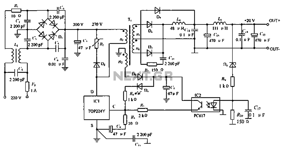
The circuit depicted in the figure is designed to achieve a higher power output by modifying specific components. On the left side of the figure, components R1, L1, D1, and capacitors C1 to C7 form a conventional filtering and...
This preamplifier uses a type of IC 741 and can boost a microphone signal to line level. The microphone signal is connected to the input port. Any power for the microphone jack of the food are met. Here half...
In addition to its primary function as a headphone amplifier, the circuit is suitable for various applications requiring a wide bandwidth low power amplifier. It is constructed using an operational amplifier (op-amp), with its output current enhanced by a...
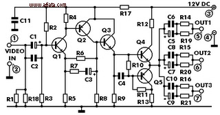
This electronic circuit is a video signal amplifier that provides a broad bandwidth amplifier with a capacity of 5 MHz. It is designed to take video signals from a VCR and amplify them adequately to drive up to three...