
relay toggle circuit using a 555 timer
The described 555 timer circuit operates in a bistable mode, utilizing the versatile 555 timer IC, which is widely employed in timing applications. The relay serves as an output device that can control higher voltage or current loads, making it suitable for various automation tasks.
In this configuration, the two 10K resistors connected to pins 2 and 6 ensure that both inputs are biased to half the supply voltage, creating a stable reference point. This configuration allows the timer to respond to changes in voltage levels effectively. The capacitor, when charged, stores energy and influences the state of the output pin (pin 3) based on the voltage levels at the trigger and threshold inputs.
Upon pressing the button, the capacitor discharges, causing a momentary drop in voltage at pins 2 and 6. This drop triggers the 555 timer to switch its output state. If the output was previously low, it will switch to high, energizing the relay and allowing current to flow through its coil. The relay contacts can then close, completing a separate circuit and powering connected devices.
When the output transitions from high to low, the capacitor begins to charge again through the 100K resistor, which determines the timing characteristics of the circuit. The discharge process ensures that the relay remains in its activated state only for a brief period, providing a controlled response to the button press. This timing can be adjusted by changing the capacitor value or the resistance of the charging resistor, allowing for customization of the circuit's operational parameters.
In summary, this 555 timer relay circuit effectively demonstrates the principles of timing and control in electronics, showcasing how simple components can be combined to create useful applications in automation and control systems.This 555 timer circuit toggles a relay when a button is pressed. Pins 2 and 6, the threshold and trigger inputs, are held at 1/2 the supply voltage by the two 10K resistors. When the output is high, the capacitor charges through the 100K resistor, and discharges when the output is low.
When the button is pressed, the capacitor voltage is applied to pins 2 and 6 which causes the output to change to the opposite state.. 🔗 External reference
Related Circuits
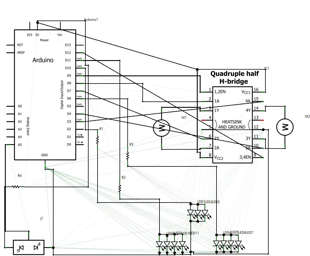
1. Abstract Wet-garden is an interactive flower garden and an ambient indoor sculpture. When people walk around it, it changes motion and LED blinking speed. Wet-design is designed for everyone who wants a tangible interaction object and an interesting...
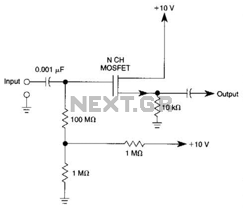
Biasing methods for an N-channel MOSFET to form a unity-gain noninverting amplifier or source-follower. The N-channel MOSFET can be utilized in various configurations, with one common application being the unity-gain noninverting amplifier, also known as a source-follower. In this configuration,...
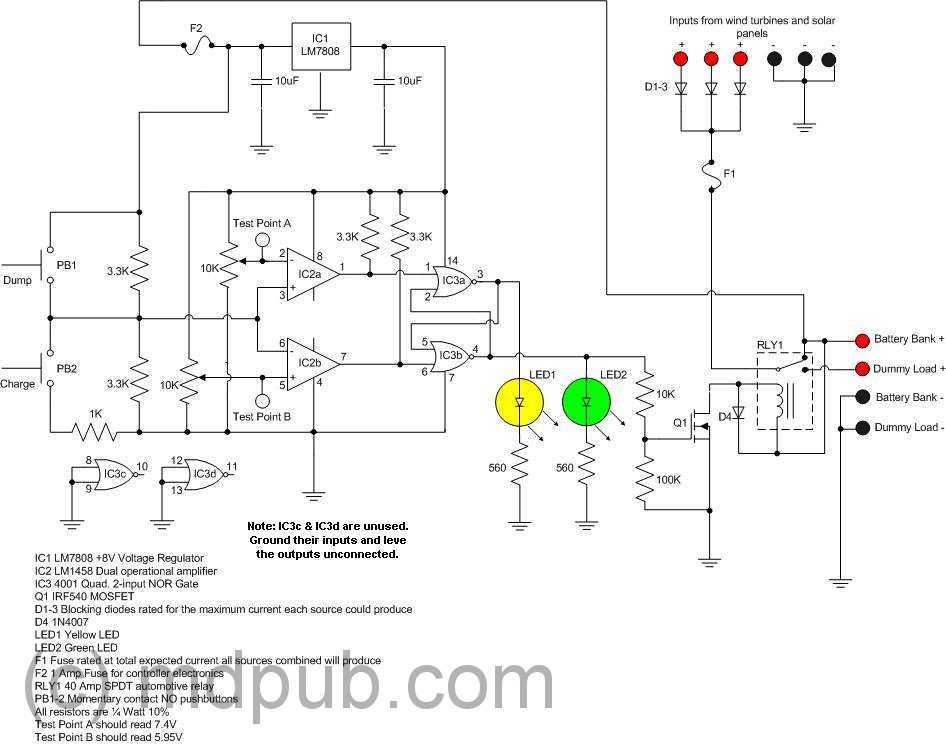
The prototype was successfully assembled on a breadboard and subsequently built on a piece of Radio Shack protoboard for field use. The assembly process took only a couple of hours, and it functioned correctly on the first attempt. This...
This voltage-to-frequency converter circuit features a voltage-controlled oscillator with a deviation of 0.5%. The integrated circuit IC1 functions as a multivibrator, generating rectangular impulses of equal width. The output frequency is adjustable via the U1 voltage. The D3 diode...
This circuit prioritizes a microphone and preamplifier (voice circuit) over any other audio signal, functioning similarly to a one-way intercom. When the push-to-talk switch is activated, the main amplifier switches from music to the voice signal. Essentially, a voice-over...
This audio noise filter circuit is a bandpass filter designed for the audio frequency range. It effectively filters out unwanted signals that fall outside the audio frequencies. The circuit consists of two filters: a low-pass filter and a high-pass...