
CMOS 4060 IC For Repeating Interval Timer
The CMOS 4060 IC is a versatile component widely used in timer and oscillator applications due to its high noise immunity and low power consumption. This integrated circuit includes a 14-stage binary ripple counter and an oscillator, which can be configured to generate a variety of timing intervals. The circuit can be designed to produce a stable output frequency by adjusting external components such as resistors and capacitors connected to the timing pins.
In a typical configuration of the repeating interval timer, the CMOS 4060 is connected to an external resistor-capacitor (RC) network. The values of these components determine the frequency of oscillation. The output from the oscillator feeds into the binary counter, which counts the pulses and can be configured to reset after a predetermined count, effectively creating a repeating timer function. The output can be taken from various stages of the counter, allowing for different timing intervals to be achieved depending on the specific application requirements.
To enhance functionality, additional components such as diodes and transistors may be included to drive higher loads or to interface with other logic levels. The circuit can be powered by a standard DC supply, making it suitable for battery-operated devices. Overall, the CMOS 4060-based repeating interval timer circuit is a reliable solution for applications requiring precise timing control.The following circuit shows about CMOS 4060 IC For Repeating Interval Timer Circuit Diagram. Features: Based On The CMOS 4060 IC, 14-bit binary .. 🔗 External reference
Related Circuits
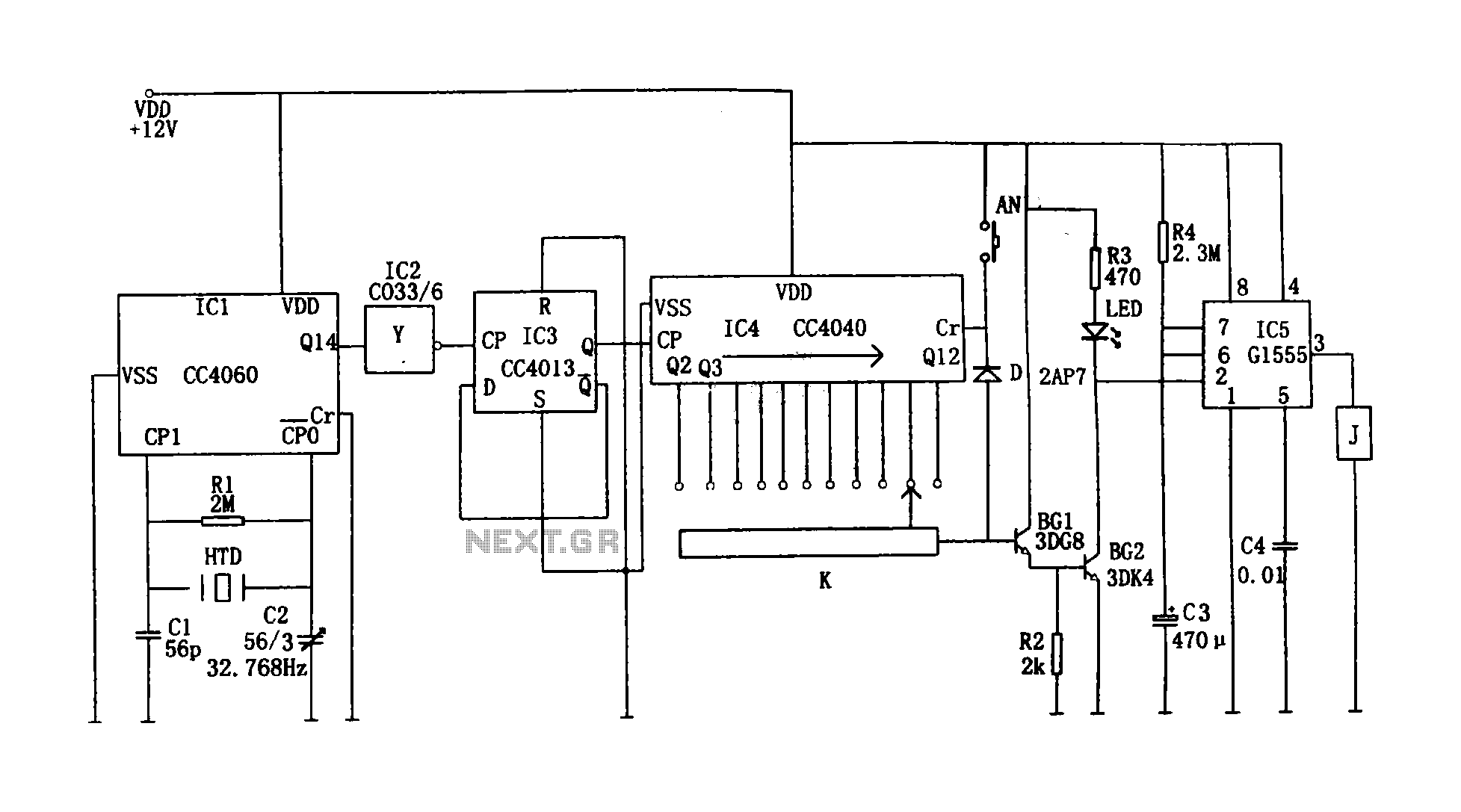
This circuit illustrates a precision digital timing control system. The controller includes a crystal oscillator circuit, a divider, a counting circuit, and monostable flip-flops. The crystal oscillator circuit features a series of 14 binary counters/dividers, a watch crystal operating...

A Siemens SLB0586A IC enables the creation of a straightforward touch-controlled dimmer circuit. This circuit regulates a triac AC switch, allowing control of loads ranging from 10 to 400 W. The Siemens SLB0586A integrated circuit is designed to facilitate the...
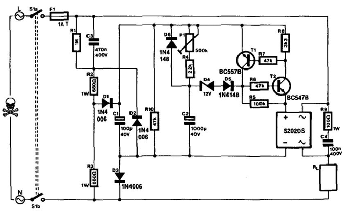
This timer can be integrated into a power line to provide a controllable delay before a load is activated. The mains voltage is reduced by capacitor C3 and rectified to yield approximately 30 V across capacitor C1. This voltage...
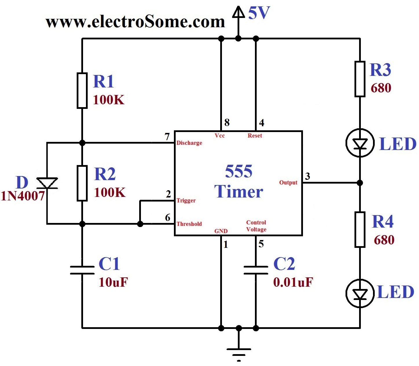
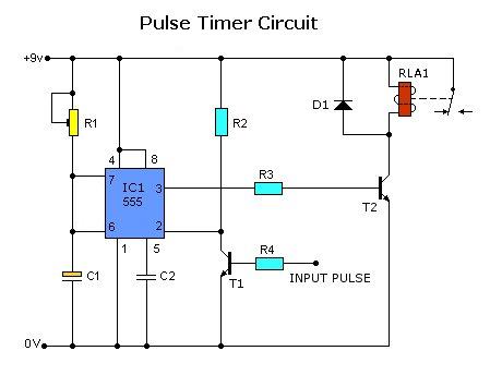
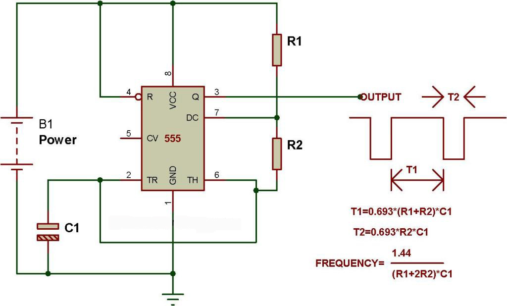
A dancing light can be easily constructed using a 555 timer wired in astable mode. This circuit alternately blinks two LEDs with a certain delay and can be modified to include additional LEDs or to control incandescent lamps. The...
Today, solutions are offered for a timed control relay that utilizes Normally Open (NO) and Normally Closed (NC) contacts to manage the operation of other devices, enabling or disabling them as needed. The functionality of this circuit is based...
The schematic presented originates from buildcircuit.com. This circuit functions as a music generator, infrared transmitter, and LED blinker, depending on the values of R1, R2, and C1. A minor modification to the previous circuit allows it to operate as...