
garage door opener circuit schematic

The schematic for the Craftsman Garage Door Opener provides a comprehensive overview of the system's electrical components and their interconnections. Typically, the schematic includes the main control board, which serves as the brain of the operation, facilitating communication between various components such as the motor, sensors, and remote control receiver.
The garage door opener system usually consists of several key parts: the motor unit, which drives the door mechanism; limit switches, which determine the fully open and closed positions of the door; safety sensors, which prevent the door from closing on obstacles; and a power supply unit, which converts AC voltage from the electrical outlet to the DC voltage required by the motor.
Installation manuals for the Craftsman Garage Door Opener provide step-by-step instructions for setting up the system, including mounting the motor unit, wiring the components, and programming the remote controls. The manuals often include diagrams that illustrate the proper connections and configurations.
In addition, the availability of replacement parts through Sears ensures that any worn or malfunctioning components can be easily replaced, maintaining the functionality and safety of the garage door opener system. With 15 years of experience, Garage Door Openers Superstore is well-equipped to provide support and guidance for both installation and maintenance of these systems, ensuring reliable operation for users.Craftsman Garage Door Opener Schematic Garage Door Opener Installation Manuals. Sears Craftsman Garage Door Opener Parts,. Garagen Beratung With 15 years in the business, Garage Door Openers Superstore is a. 🔗 External reference
Related Circuits
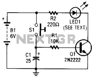
Used as a 10-second momentary illuminator, this circuit can be useful in other applications as well. Pressing SI charges CI, which holds Q1 on and keeps the LED lit for about 10 seconds. The circuit described functions as a momentary...

Although LEDs dominate the lighting market today, a standard flashlight bulb can still be a viable light-emitting option, particularly due to its simpler configuration compared to an LED. When the AC mains supply fails, transistor T1 becomes forward-biased, allowing...
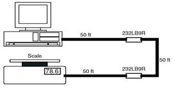
This is the schematic diagram of a 9-Pin RS232 Line Booster Signal Direction. The device functions as a 9-pin RS-232 repeater, re-transmitting all 8 signals while also maintaining the ground line. The 9-Pin RS232 Line Booster is designed to extend...
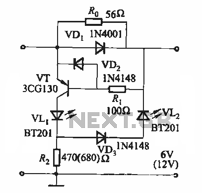
During the charging process, the green light-emitting diode (LED) VLi indicates that the battery is sufficiently charged, while the red light-emitting diode (LED) VLz illuminates when the battery is low. The circuit involves two light-emitting diodes (LEDs) serving as indicators...
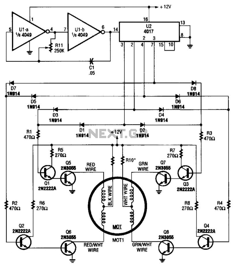
A 4017 decade counter/divider, driven by a low-frequency oscillator (U1-a and U1-b), is employed to control transistor switches that sequence the motor windings as required. The motor (MOT1) is a 12-V stepper motor. Resistors R9 and R10 are chosen...
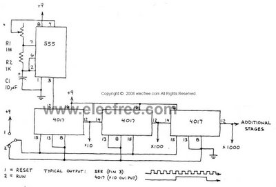
This circuit is designed to provide long time delays using the integrated circuit Timer 555. It utilizes the NE555 to generate pulse frequencies, which are then divided by a 4017 decade counter to achieve the desired delay. The component...