
Gate Deep Oscillator
To build it, particular experience in radio-frequency assembly is required. First of all, remember to keep all connections as short as possible; otherwise, problems may arise above 50 MHz. Coils are built as shown later using a 5-pin DIN plug.
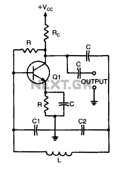
The circuit operates by utilizing a BF245 or K161 FET as the active component, which is configured in a common-source configuration to provide the necessary gain and oscillation. The frequency of oscillation can be adjusted by changing the inductance of the coil connected to the circuit. This is typically achieved through a variable inductor or by using a switchable arrangement of fixed inductors.
The oscillator is powered by a suitable DC voltage source, typically within the range of 9V to 15V, ensuring that the FET operates within its specified limits. The output can be taken from the drain of the FET, where a buffer stage may be added if necessary to match the impedance of the load or for further processing of the signal.
The 100 microA meter serves as a tuning indicator, allowing the user to monitor the current flowing through the circuit, which correlates with the oscillation frequency. This feature is particularly beneficial for tuning the output to specific frequencies required for testing various radio components.
The use of a metal case is crucial for shielding the oscillator from external electromagnetic interference, which can affect performance, especially at higher frequencies. The double-sided vetronite board serves as the substrate, with one side dedicated to the ground plane, reducing noise and improving stability.
When assembling the circuit, it is essential to minimize the length of the connections to prevent inductive and capacitive coupling that could distort the oscillation frequency, especially above 50 MHz. The coils should be constructed according to specific dimensions and winding techniques to ensure the desired inductance values are achieved.
Overall, this variable oscillator circuit is a valuable tool for radio frequency experimentation and development, providing flexibility in frequency generation and reliable performance when properly constructed and housed.It`s just a variable oscillator based on a bf245 or k 161 fet. By changing the coil it can generate frequency between 0.5 and 300 MHZ. this circuit is useful to test radio circuit such as filter, receiver, transmitter and so on . It can be use for coil tuning thanks to the 100microA meter .It must be placed in a metal case but I`ve used a double sided vetronite board, one for ground. To build it , is requested particular experience in radio-frequency assembling . First of all remember to put as short as possible all connections or you`ll have problems over 50 MHZ. .Coils are build as shown later using a 5 pins DIN plug . The cent 🔗 External reference
Related Circuits
This circuit is a crystal oscillator that operates at a frequency of 3.5 MHz. The crystal oscillator circuit utilizes a quartz crystal resonator to generate a stable frequency output. The primary components typically include the crystal, an amplifier (often a...
This result places the oscillator within the UK FM Band, which ranges from 87.5 to 108 MHz. If L1 is equipped with an adjustable ferrite core, its inductance can be modified, allowing for fine tuning. If L1 consists of...
When calculating the resonant frequency, use the formula C1C2/(C1+C2) for the total capacitance of the L-C circuit. In an L-C (inductor-capacitor) circuit, the resonant frequency is a critical parameter that determines the frequency at which the circuit will oscillate. The...
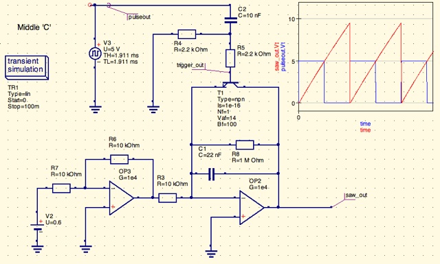
A design for a digitally controlled analog oscillator is being developed. The control voltage is generated by a microcontroller (Arduino) and is utilized through two operational amplifiers, along with a resistor and capacitor network that forms an integrator circuit....
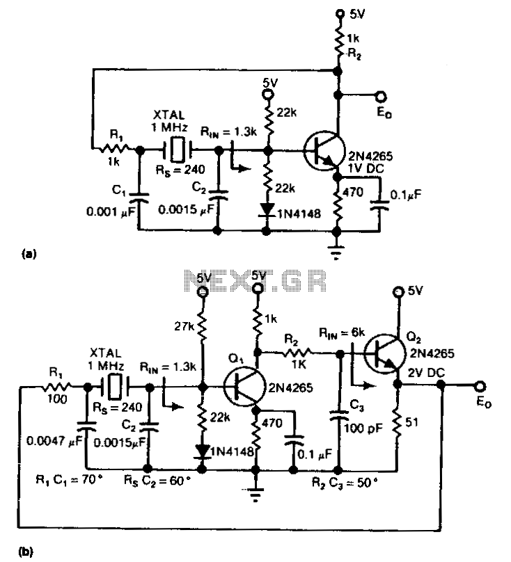
This circuit is a conventional Pierce type oscillator that utilizes a JFET. It employs fundamental mode crystals and demonstrates decent performance and reliability. The Pierce oscillator is a popular configuration for generating stable oscillations, particularly in applications requiring a stable...
The circuit is an inverter configured as a linear amplifier. By incorporating a crystal and capacitors into the feedback path, the amplifier is transformed into an oscillator, enabling it to oscillate at or near the crystal's resonant frequency. Trimmer...