
Colpitts oscillator
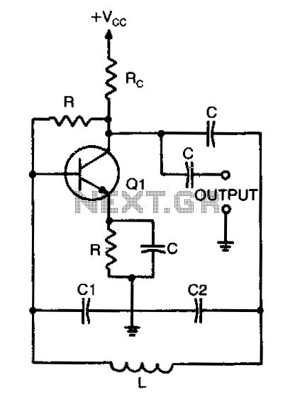
In an L-C (inductor-capacitor) circuit, the resonant frequency is a critical parameter that determines the frequency at which the circuit will oscillate. The resonant frequency can be calculated using the total capacitance of the circuit, which is derived from the individual capacitances of capacitors C1 and C2 connected in parallel. The formula C_total = C1C2/(C1+C2) is used to compute the total capacitance when capacitors are in parallel, allowing for an accurate assessment of the circuit's behavior at resonance.
The resonant frequency (f_r) can then be calculated using the formula:
f_r = 1 / (2π√(L * C_total))
Where L is the inductance of the inductor in the circuit. This equation shows how the resonant frequency is inversely proportional to the square root of the product of inductance and total capacitance. Understanding this relationship is essential for designing circuits that require precise frequency tuning, such as oscillators, filters, and radio transmitters. Proper calculation of the total capacitance and resonant frequency ensures optimal performance and stability of the circuit.When calculating its resonant frequency, use C1C2/C1+C2 for the total capacitance of theL-C circuit. 🔗 External reference
Related Circuits
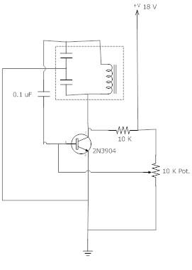
The frequency remains stable as the voltage decreases. It is referred to as the "backwards JT" because it operates optimally with a bifilar coil and a single transistor. With a modification to the circuit, it is possible to deplete...
A frequency reference for tuning up the RS-232 to 100 MHz RF desktop channel adapter elsewhere on this site, when I found this Saronix crystal oscillator in my junk box. A few minutes with AVRStudio produced an ATtiny12 to...
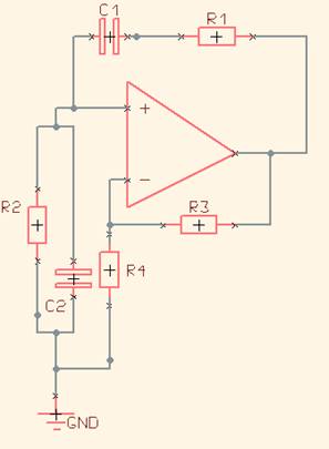
One of the simplest sine wave oscillators is the Wien Bridge Oscillator. Any circuit requires two conditions to oscillate. Tracing the path from the input, through the feedback network, and back to the input, there must be an overall...
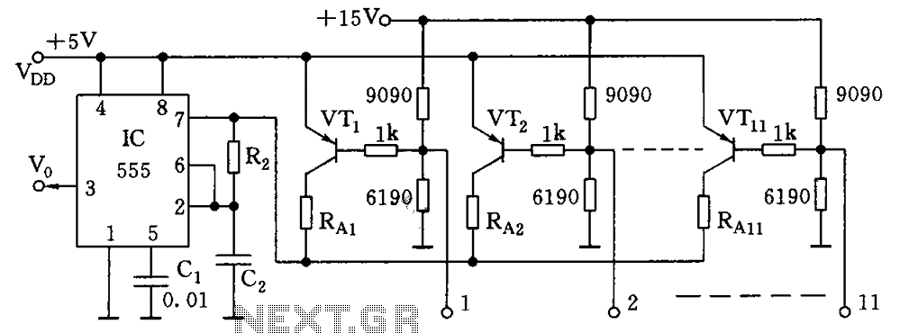
As illustrated in the figure, the base bias circuit for transistors VT1 to VT11 is designed to accept binary data, where a high level represents 1 and a low level represents 0. This configuration allows for 2048 combinations of...
The single-813 crystal oscillator transmitter, designed by RCA, was showcased in an advertisement on the back page of a 1938 "QST" magazine and published in the RCA HamTips bulletin, volume 1, number 4, dated December 1938. This transmitter delivers...
An oscillator can be constructed using an LC (inductor-capacitor) tank circuit. By varying the capacitance of the capacitor in the LC tank circuit, the frequency of the oscillator can be adjusted. An LC tank circuit serves as a fundamental building...